Optimal aircraft design is impossible without a parametric representation of the geometry of the airframe. We need a mathematical model equipped with a set of controls, or design variables, which generates different candidate airframe shapes in response to changes in the values of these variables. This model's objectives are to be flexible and concise, and capable of yielding a wide range of shapes with a minimum number of design variables. Moreover, the process of converting these variables into aircraft geometries must be robust. Alas, flexibility, conciseness and robustness can seldom be achieved simultaneously.
Aircraft Aerodynamic Design: Geometry and Optimization addresses this problem by navigating the subtle trade-offs between the competing objectives of geometry parameterization. It beginswith the fundamentals of geometry-centred aircraft design, followed by a review of the building blocks of computational geometries, the curve and surface formulations at the heart of aircraft geometry. The authors then cover a range of legacy formulations in the build-up towards a discussion of the most flexible shape models used in aerodynamic design (with a focus on lift generating surfaces). The book takes a practical approach and includes MATLAB®, Python and Rhinoceros® code, as well as 'real-life' example case studies.
Key features:
Covers effective geometry parameterization within the context of design optimization
Demonstrates how geometry parameterization is an important element of modern aircraft design
Includes code and case studies which enable the reader to apply each theoretical concept either as an aid to understanding or as a building block of their own geometry model
Accompanied by a website hosting codes
Aircraft Aerodynamic Design: Geometry and Optimization is a practical guide for researchers and practitioners in the aerospace industry, and a reference for graduate and undergraduate students in aircraft design and multidisciplinary design optimization.
Trusted by 375,005 students
Access to over 1.5 million titles for a fair monthly price.
Geometry is the lingua franca of engineering. Any conversation around a nontrivial design problem usually has even the most articulate engineer overcome, within minutes, by the desire to draw, sketch or doodle. Over the centuries the sketching tools have changed. However, Leonardo da Vinci wielded his chalk and pen for the same reason why today’s engineers slide their fingertips along tablet computer screens, deftly creating three-dimensional geometrical models and navigating around them: the functionality and performance of an engineering product depends, to a very large extent, on its shape and size; that is, on its geometry.
Different fields of engineering place different levels of emphasis on geometry, but perhaps none focuses on it more sharply than the aerodynamic design of aircraft. The goal of the aerodynamics engineer is to create an object that, when immersed in airflow, will change the patterns of the latter in a desirable fashion,1 and this is most readily achieved through the shaping and sizing of the object.
Sadly for aerodynamic engineers, their freedom to play with the form of the aircraft’s flow-wetted surfaces is often curtailed by other departments competing for influence over the same piece of real estate: structural engineering, cost modelling, propulsion, control systems, cabin and payload, and so on. Moreover, the aerodynamic performance of an aircraft is usually multifaceted too: different phases of the same mission tend to drive the external shape in different directions. This tension between competing objectives is usually resolved in one of three ways:
One of the goals trumps all others. The shape usually gives this away – it is immediately clear to the trained observer that one interest drove the design of the aircraft and the others had to operate within very strict constraints defined by it.
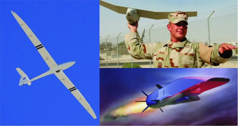
Consider Figure 1.1 as an example. It shows three unmanned aircraft. One has a delicate-looking, sleek airframe with very long and narrow wings: a glider (sailplane), the design of which was driven by the single-minded desire to maximize endurance. The structural and cost engineers would no doubt have liked to have seen shorter, stubbier wings, upon which the air loads generate lighter bending moments, but this was a case of shape design in the service of aerodynamic efficiency, with little more than a glance toward other objectives.
The top right image shows a soldier launching a low-altitude, low-endurance surveillance platform. The ‘boxy’ fuselage and the short, wide wings identify this as a design driven by a desire for ruggedness and enough spare structural strength to allow the aircraft to cope with the rough handling likely in a battlefield environment – at the expense of aerodynamic efficiency.
Finally, the third picture shows a hypersonic research aircraft. It is not able to carry any payload, it has no landing gear (it is a single-use vehicle) and its endurance is measured in seconds. But it does ‘ace’ one objective: speed. Every feature of its geometry says ‘designed for a hypersonic dash’ (more on this extraordinary vehicle in the next chapter).
A compromise results, which balances all the competing goals. How to analyse all the trade-offs involved and how to make design decisions based on them is the core question of modern engineering design and we will discuss some of the relevant techniques in Chapter 2.
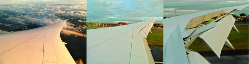
The ‘all things to all departments’ solution. The aircraft, or aircraft subsystem, is actually several designs rolled into the same packaging, with each design optimized for a particular goal. An in-flight ‘morphing’ process mutates the geometry from one shape to another, depending on the phase of the mission. Perhaps the most common embodiment of this principle is the high-lift system that enables many aircraft to cruise efficiently at high speed, but also generates sufficient lift at the low speeds typical of take-off and landing (see Figure 1.2).
This is a complex problem for the designer, as the challenge is not only to design multiple geometries, each optimized for, say, different flow regimes, but also to choreograph the transition process – all this without exceeding weight, cost and complexity constraints.
Figure 1.1 Three unmanned air vehicles (UAVs), three main design drivers: NASA Towed Glider Air-Launch Concept (left, NASA image) – long endurance at low speeds; AeroVironment RQ-11 Raven (top right, USAF image) – structural robustness to cope with battlefield conditions; Boeing X-51 (USAF image) – extremely high speed.
Figure 1.2 Three wing geometries packaged into one and able to morph from one to another: the trailing edge of the wing of a Boeing 787-8 airliner in (from left to right) cruising flight, final approach and touch-down (photographs by A. Sóbester).
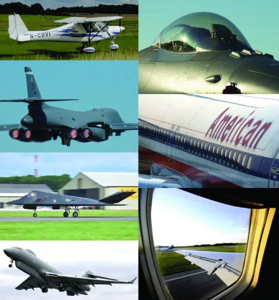
Ultimately, the external geometry of an aircraft results from the systematic analysis of the physics behind all the relevant objectives and constraints and the application of engineering optimization techniques to the resulting data to generate a solution that satisfies the design brief. There is an almost endless diversity of design briefs, of different relative importances of the objectives, of physics-based performance simulation capabilities and of design techniques, the result being an immense range of shapes – see Figure 1.3 for a small selection. This diversity is a measure of how serious a mathematical challenge shape modelling is.
Figure 1.3 External (or outer mould line) geometry – even within the realm of fixed-wing aircraft, the variety and sophistication of surface shapes poses a serious geometry modelling and optimal design challenge (photographs by A. Sóbester).
In terms of an aeronautical engineer’s relationship with geometry, much has changed since da Vinci began sketching flying vehicles. This technological transformation has been a nonlinear one too, with the migration from a two-dimensional drawing board into the three-dimensional space of virtual geometries stored in the memory of a computer constituting the greatest leap. However, the most important aspect of this revolution that began to gather momentum in the 1970s and 1980s was not the extension into the third dimension.
Rather, with the advent of the first computational geometry engines, engineers were suddenly able to make local, as well as large-scale, changes to the emerging geometry in a systematic and time-efficient manner. This step was particularly significant at the level of whole aircraft geometries – no longer did the change of a simple dimension on one component mean that tens or hundreds of other blueprints had to be redrawn. Instead, the computational geometry cascaded the changes as appropriate, and thus new configurations could be generated in a matter of seconds.
At the component level, generating hundreds or thousands of different candidate shapes became possible, which, in combination with the emerging field of numerical analysis codes capable of simulating the performance of these shapes, gave engineers a powerful design tool.
This new capability created a need for developments in the mathematics of shapes of relevance to aerodynamic design. A new breed of curve and surface models was needed that was equipped with simple handles: design variables, the values of which could be altered, leading to intuitive shape changes. This had previously been of little interest, as redrawing a blueprint or sanding the wind tunnel model of a geometry to a slightly adjusted shape had not required such formalisms.
The Hicks–Henne basis functions mentioned in the Preface (we will return to it later in this text) were one example of such developments. At the same time a much older idea gained a ‘second life’.
In the 1930s, long before the earliest electronic computers, the National Advisory Committee for Aeronautics (NACA) had developed a wing section model defined through two pairs of parametric polynomials. By altering the parameter values, a family of designs could be built up, comprising airfoils suitable for a wide range of applications. As we shall see in Chapter 6, members of this family are still ‘in service’ eight decades later on a number of aircraft. But, perhaps even more importantly, in the new era of computational geometry modelling and numerical flow simulation the NACA sections suddenly became the template for just the type of mathematical formulation demanded by the new technology. The three components of the modern computational design process architecture, as we know it today, crystallized: a parametric shape desc...
Table of contents
Cover
Aerospace Series List
Title Page
Copyright
Series Preface
Preface
Chapter 1: Prologue
Chapter 2: Geometry Parameterization: Philosophy and Practice
Chapter 3: Curves
Chapter 4: Surfaces
Chapter 5: Aerofoil Engineering: Fundamentals
Chapter 6: Families of Legacy Aerofoils
Chapter 7: Aerofoil Parameterization
Chapter 8: Planform Parameterization
Chapter 9: Three-Dimensional Wing Synthesis
Chapter 10: Design Sensitivities
Chapter 11: Basic Aerofoil Analysis: A Worked Example
Chapter 12: Human-Powered Aircraft Wing Design: A Case Study in Aerodynamic Shape Optimization
Yes, you can cancel anytime from the Subscription tab in your account settings on the Perlego website. Your subscription will stay active until the end of your current billing period. Learn how to cancel your subscription
No, books cannot be downloaded as external files, such as PDFs, for use outside of Perlego. However, you can download books within the Perlego app for offline reading on mobile or tablet. Learn how to download books offline
Perlego offers two plans: Essential and Complete
Essential is ideal for learners and professionals who enjoy exploring a wide range of subjects. Access the Essential Library with 800,000+ trusted titles and best-sellers across business, personal growth, and the humanities. Includes unlimited reading time and Standard Read Aloud voice.
Complete: Perfect for advanced learners and researchers needing full, unrestricted access. Unlock 1.5M+ books across hundreds of subjects, including academic and specialized titles. The Complete Plan also includes advanced features like Premium Read Aloud and Research Assistant.
Both plans are available with monthly, semester, or annual billing cycles.
We are an online textbook subscription service, where you can get access to an entire online library for less than the price of a single book per month. With over 1.5 million books across 990+ topics, we’ve got you covered! Learn about our mission
Look out for the read-aloud symbol on your next book to see if you can listen to it. The read-aloud tool reads text aloud for you, highlighting the text as it is being read. You can pause it, speed it up and slow it down. Learn more about Read Aloud
Yes! You can use the Perlego app on both iOS and Android devices to read anytime, anywhere — even offline. Perfect for commutes or when you’re on the go. Please note we cannot support devices running on iOS 13 and Android 7 or earlier. Learn more about using the app
Yes, you can access Aircraft Aerodynamic Design by András Sóbester,Alexander I J Forrester,Alexander I. J. Forrester, Peter Belobaba, Jonathan Cooper, Allan Seabridge, Peter Belobaba,Jonathan Cooper,Allan Seabridge in PDF and/or ePUB format, as well as other popular books in Technology & Engineering & Aeronautic & Astronautic Engineering. We have over 1.5 million books available in our catalogue for you to explore.