![]()
Chapter 1
Introduction
Fuel cells are electrochemical devices that directly convert chemical energy into electrical energy. As the production of energy in fuel cells does not involve any moving parts and their principle of operation varies from that of heat engines, the energy produced by these cells is neither associated with any mechanical friction loss nor limited by Carnot cycle efficiency. Moreover, the unreacted fuel from the cell can be used to generate more power. The overall efficiency of the cell can also be increased by recovering the heat generated during operation from the exhaust gas.
Today's energy-hungry civilisation is in search of an alternative source to replace the currently available but continuously depleting conventional energy sources. Stringent environmental regulations have restricted the emission of greenhouse gases, SOx and NOx, and hence narrowed down the search for a clean source of energy to a few options. These are the main reasons behind the growing interest in the development of fuel cells as an alternative source of clean energy.
However, there are a number of obstacles in the commercialisation of fuel cells as a main source of energy. The main obstacle comes from the high manufacturing cost of the fuel cell. A vast amount of research is being conducted on the design and operation of fuel cells for reducing the cost and hence turning these devices into a viable and competitive source of energy. Selections of materials for electrolyte, catalyst and electrodes also contribute to the cost of a fuel cell. A number of researchers have focussed on this area. It is often required to simulate the fuel cell system under different operating conditions to account for all the pitfalls associated with the design and material selections. Depending on the perspective, the modelling and simulation can range from micro to system levels. This book focuses on solid oxide fuel cell system from the perspective of process control for the safe and efficient operation of the fuel cell system as a power source. It includes control relevant modelling, state estimation and controller design.
1.1 Overview of Fuel Cell Technology
Construction of a unit fuel cell mainly consists of three parts—electrolyte, cathode and anode. Fuel is continuously fed into the anode of the fuel cell, and a suitable oxidant, usually air, is fed into the cathode. The main purpose of the electrolyte is to prevent direct contact of the fuel with the oxidant while connecting the anode and cathode electrically. The electrolyte also allows the passage of the oxidant or reductant ions to the other side to take part in the electrochemical reaction.
1.1.1 Types of Fuel Cells
The classification of fuel cells is based on the choice of electrolyte and fuel. They are as follows:
- Solid Oxide Fuel Cell (SOFC): Solid oxide fuel cell uses a solid ceramic type oxide, and thus receives the name. Y2O3 stabilised ZrO2 (YSZ) is a common electrolyte used in SOFCs. The operating temperature of the fuel cell is usually high (600–1000 °C). Owing to the solid nature of the electrolyte and electrodes, the SOFC can be designed and fabricated in the most versatile ways, including planar and tubular designs.
- Molten Carbonate Fuel Cell (MCFC): Molten carbonate fuel cells use different combinations of alkali carbonates as an electrolyte. These carbonates are usually contained in a ceramic matrix. The operating temperature of MCFCs is also high, usually between 600 and 700 °C.
- Proton Exchange Membrane Fuel Cell (PEMFC): In this type of fuel cell, a polymeric ion exchange membrane is used as an electrolyte. The operating temperature of these cells is usually low (40–80 °C).
- Phosphoric Acid Fuel Cell (PAFC): The electrolyte in the PAFC is 100% phosphoric acid, which is held in a silicon carbide structure. The operating temperature of the fuel cell is about 150–220 °C, which is one of the attractive features of PAFC. This operating temperature makes it flexible to design the fuel cell and the balance of plant (BOP).
Other types of fuel cells include alkaline fuel cell (AFC), direct methanol fuel cell (DMFC), regenerative fuel cell (RFC) and metal air fuel cell (MAFC). Fue (2004) provides a summary of major differences in different types of fuel cells.
The low-temperature PEMFC and the high-temperature SOFC have been identified as the likely fuel cell technologies that will capture the most significant market in the future.
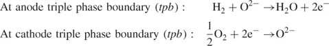
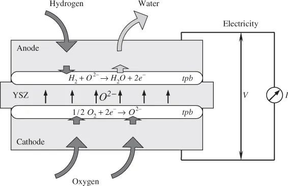
The basic principle of a typical hydrogen SOFC is shown in Figure 1.1. The chemical reactions inside the cell, which are directly involved in the production of electricity, are as follows:
At the anode of the SOFC, hydrogen gas reacts with oxygen ions that are migrated through the electrolyte to form water and release electrons. At the cathode, oxygen ionises with electrons and creates O2− ions. O2− ions are transported to anode through the electrolyte. Electrons produced at the anode flow through an external electrical circuit and reach the cathode. These reactions, therefore, both proceed continuously and supply electricity to the external circuit. Usually, SOFCs work at a high temperature, in the range of 600–1000 °C, to meet the electrolyte's ionic conductivity requirement.
Hydrogen used as the fuel for SOFCs can be produced by steam reforming of natural gas. For a high-temperature fuel cell such as SOFC, the reforming reaction can be performed internally, within the anode of the cell.
1.1.2 Planar and Tubular Designs
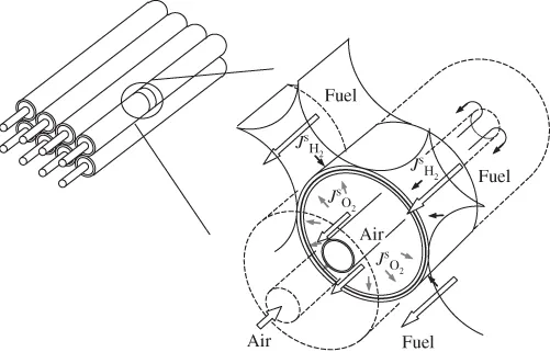
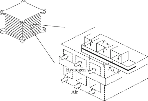
To meet the voltage requirement for most of the applications, fuel cell systems need to be composed of stacks of connected individual cells. An SOFC stack is composed of a number of SOFC cells to produce a high voltage output. In designing SOFC stack and cells, there are many factors that need to be considered, such as gas delivery, thermal stresses, mechanical strength, inherent electrical and ionic resistance and choice of seal materials. SOFCs are manufactured in various geometries, the most common of which are the planar and tubular designs shown in Figures 1.2 and 1.3, respectively.
One of the most important advantages of the tubular design is that it does not need the seal to separate fuel and air flow. Another advantage is that the tubular shape can improve the strength of the cell. The tubular shape can also improve the gas delivering property. This kind of design is suitable for stationary and large-scale power generation applications.
On the other hand, the most significant advantage of the planar SOFC design is its lower electrical resistance. Planar SOFCs are more suitable for mobile and low power applications.
1.1.3 Fuel Cell Systems
In an ideal fuel cell, hydrogen is used as a fuel along with air as an oxidant. Such a fuel cell can work as the cleanest possible source of energy—the by-product of the reaction being water. However, as hydrogen is not readily available in nature, in practice, the hydrogen used as fuel for these systems needs to be produced from other sources. Hydrogen-rich fuels are most commonly used to produce hydrogen either internally or externally to the fuel cell. Thus, a fuel cell plant usually involves components for pre- and post-processing of the reactants and products. The components, which are also called BOP, may include compressors, turbines, heat exchangers, reactors for reforming of the fuel and a DC–AC converter or inverter to connect the fuel cell to an existing power grid.
Compressors or blowers are required to build necessary pressure to pass reactants and products through different components. The unreacted fuel from the fuel cell itself can be combusted in a gas turbine for generating more power. The compressor–turbine duo thus provides a net power in addition to the direct power generated by the fuel cell itself. In residential applications, the hot effluent gas can be used to supply hot water and provide heat for the households.
A fuel cell directly converts chemical energy into electrical energy. The output being a DC voltage is appropriate to operate small equipment. For a fuel cell power plant, the DC power needs to be converted to AC in order to be transferable to the power supply grid. Thus, the BOP may also include a power conditioning unit (PCU).
1.1.4 Pros and Cons of Fuel Cells
Fuel cells have various advantages over conventional power generation systems such as batteries and turbines. As with any other technology, a fuel cell comes with some advantages and disadvantages. Some of these are described below.
Advantages:
- Unlike turbines, a fuel cell system does not have any moving components, and thus does not have any mechanical friction loss associated with it. It also provides a quiet operation and less maintenance.
- Unlike a heat engine, a fuel cell converts chemical energy directly into electrical energy. Thus, it is not limited by Carnot cycle efficiency.
- The exhaust (unreacted fuel) gas from the fuel cell can be used to generate excess power by coupling with a heat engine, thereby, increasing the efficiency.
- The efficiency of a fuel cell is not limited by size. Thus, a small fuel cell powering a laptop or a personal electronic gadget can generate power at the same efficiency as a 10 MW fuel cell power plant.
- A wide range of fuels may be used for fuel cells.
- As the reaction inside a fuel cell occurs between specific ions only, it limits the release of NOx and SOx to the environment.
Disadvantages:
- Fuel cells are expensive compared to other energy producing technologies at least at the moment.
- Most fuel cells use hydrogen as fuel, and it impedes commercialisation of these devices because of the cost and complexities associated with the production, storage and transportation of hydrogen.
- In comparison with batteries, fuel cells have lower power densities and shorter lifetimes.
- Impurity of fuel gas may poison catalysts in electrodes.
1.2 Modelling, State Estimation and Control
Process modelling, state estimation and design of the controller are part of advanced process control strategies. They are intricately dependent on each other. For example, building a model (whether it ...