Robert M. Del Vecchio, Bertrand Poulin, Pierre T. Feghali, Dilipkumar Shah, Rajendra Ahuja
This is a test
This is a test
Buch teilen
596 Seiten
English
ePUB (handyfreundlich)
Über iOS und Android verfügbar
eBook - ePub
Transformer Design Principles, Third Edition
Robert M. Del Vecchio, Bertrand Poulin, Pierre T. Feghali, Dilipkumar Shah, Rajendra Ahuja
Angaben zum Buch
Buchvorschau
Inhaltsverzeichnis
Quellenangaben
Über dieses Buch
In the newest edition, the reader will learn the basics of transformer design, starting from fundamental principles and ending with advanced model simulations. The electrical, mechanical, and thermal considerations that go into the design of a transformer are discussed with useful design formulas, which are used to ensure that the transformer will operate without overheating and survive various stressful events, such as a lightning strike or a short circuit event. This new edition includes a section on how to correct the linear impedance boundary method for non-linear materials and a simpler method to calculate temperatures and flows in windings with directed flow cooling, using graph theory. It also includes a chapter on optimization with practical suggestions on achieving the lowest cost design with constraints.
Häufig gestellte Fragen
Wie kann ich mein Abo kündigen?
Gehe einfach zum Kontobereich in den Einstellungen und klicke auf „Abo kündigen“ – ganz einfach. Nachdem du gekündigt hast, bleibt deine Mitgliedschaft für den verbleibenden Abozeitraum, den du bereits bezahlt hast, aktiv. Mehr Informationen hier.
(Wie) Kann ich Bücher herunterladen?
Derzeit stehen all unsere auf Mobilgeräte reagierenden ePub-Bücher zum Download über die App zur Verfügung. Die meisten unserer PDFs stehen ebenfalls zum Download bereit; wir arbeiten daran, auch die übrigen PDFs zum Download anzubieten, bei denen dies aktuell noch nicht möglich ist. Weitere Informationen hier.
Welcher Unterschied besteht bei den Preisen zwischen den Aboplänen?
Mit beiden Aboplänen erhältst du vollen Zugang zur Bibliothek und allen Funktionen von Perlego. Die einzigen Unterschiede bestehen im Preis und dem Abozeitraum: Mit dem Jahresabo sparst du auf 12 Monate gerechnet im Vergleich zum Monatsabo rund 30 %.
Was ist Perlego?
Wir sind ein Online-Abodienst für Lehrbücher, bei dem du für weniger als den Preis eines einzelnen Buches pro Monat Zugang zu einer ganzen Online-Bibliothek erhältst. Mit über 1 Million Büchern zu über 1.000 verschiedenen Themen haben wir bestimmt alles, was du brauchst! Weitere Informationen hier.
Unterstützt Perlego Text-zu-Sprache?
Achte auf das Symbol zum Vorlesen in deinem nächsten Buch, um zu sehen, ob du es dir auch anhören kannst. Bei diesem Tool wird dir Text laut vorgelesen, wobei der Text beim Vorlesen auch grafisch hervorgehoben wird. Du kannst das Vorlesen jederzeit anhalten, beschleunigen und verlangsamen. Weitere Informationen hier.
Ist Transformer Design Principles, Third Edition als Online-PDF/ePub verfügbar?
Ja, du hast Zugang zu Transformer Design Principles, Third Edition von Robert M. Del Vecchio, Bertrand Poulin, Pierre T. Feghali, Dilipkumar Shah, Rajendra Ahuja im PDF- und/oder ePub-Format sowie zu anderen beliebten Büchern aus Tecnologia e ingegneria & Ingegneria elettronica e telecomunicazioni. Aus unserem Katalog stehen dir über 1 Million Bücher zur Verfügung.
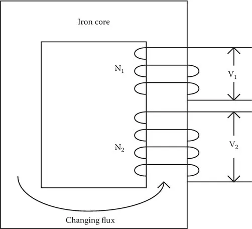
Transformers are electrical devices that change or transform voltage levels between two circuits. In the process, current values are also transformed. However, the power transferred between the circuits is unchanged, except for a typically small loss that occurs in the process. This transfer only occurs when alternating current (a.c.) or transient electrical conditions are present. Transformer operation is based on the principle of induction, formulated by Faraday in 1831. He found that when a changing magnetic flux links a circuit, a voltage or electro-motive force (emf) is induced in the circuit. The induced voltage is proportional to the number of turns linked by the changing flux. Thus, when two circuits are linked by a common flux and there are different linked turns in the two circuits, there will be different voltages induced. This situation is shown in Figure 1.1 where an iron core is shown carrying the common flux. The induced voltages V1 and V2 will differ since the linked turns N1 and N2 differ.
FIGURE 1.1 Transformer principle illustrated for two circuits linked by a common changing flux.
Devices based on Faraday’s discovery, such as inductors, were little more than laboratory curiosities until the advent of a.c. electrical systems for power distribution, which began toward the end of the nineteenth century. Actually, the development of a.c. power systems and transformers occurred almost simultaneously since they are closely linked. The invention of the first practical transformer is attributed to the Hungarian engineers Karoly Zipernowsky, Otto Blathy, and Miksa Deri in 1885 [Jes97]. They worked for the Hungarian Ganz factory. Their device had a closed toroidal core made of iron wire. The primary voltage was a few kilovolts and the secondary about 100 V. It was first used to supply electric lighting.
Modern transformers differ considerably from these early models but the operating principle is still the same. In addition to transformers used in power systems, which range in size from small units that are attached to the tops of telephone poles to units as large as a small house and weighing hundreds of tons, there are a myriad of transformers used in the electronics industry. The latter range in size from units weighing a few pounds, which are used to convert electrical outlet voltage to lower values required by transistorized circuitry, to micro-transformers, which are deposited directly onto silicon substrates via lithographic techniques.
Needless to say, we will not be covering all of these transformer types here in any detail, but will instead focus on the larger power transformers. Nevertheless, many of the issues and principles discussed are applicable to all transformers.
1.2Uses in Power Systems
The transfer of electrical power over long distances becomes more efficient as the voltage level rises. This can be shown by considering a simplified example. Suppose we wish to transfer power P over a long distance. In terms of the voltage V and line current I, this power can be expressed as
(1.1)
Let’s assume that the line and load at the other end are purely resistive so that V and I are in phase, that is, V and I are real quantities for the purposes of this discussion. For a line of length L and cross-sectional area A, its resistance is given by
(1.2)
where ρ is the electrical resistivity of the line conductor. The line or transmission losses are
(1.3)
and the voltage drop in the line is
(1.4)
Substituting for I from (1.1), the loss divided by the input power and voltage drop divided by the input voltage are
(1.5)
Since P is assumed given, the fractional loss and voltage drop for a given line resistance are greatly reduced as the voltage is increased. However, there are limits to increasing the voltage, such as the availability of adequate and safe insulation structures and the increase of corona losses.
Looking at (1.5) from another point of view, we can say that for a given input power and fractional loss or voltage drop in the line, the line resistance increases as the voltage squared. From (1.2), since L and ρ are fixed, an increase in R with V implies a wire area decrease so that the wire weight per unit length decreases. This implies that power at higher voltages can be transmitted with less weight of line conductor at the same line efficiency as measured by line loss divided by power transmitted.
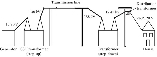
In practice, long distance power transmission is accomplished with voltages in the range of 100–500 kV and more recently with voltages as high as 765 kV. These high voltages are, however, incompatible with safe usage in households or factories. Thus, the need for transformers is apparent to convert these to lower levels at the receiving end. In addition, generators are, for practical reasons such as cost and efficiency, designed to produce electrical power at voltage levels of ~10 to 40 kV. Thus, there is also a need for transformers at the sending end of the line to boost the generator voltage up to the required transmission levels. Figure 1.2 shows a simplified version of a power system with actual voltages indicated. GSU stands for generator step-up transformer.
FIGURE 1.2 Schematic drawing of a power system.
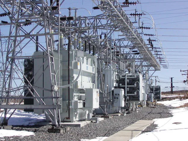
In modern power systems, there is usually more than one voltage step-down from transmission to final distribution, each step-down requiring a transformer. Figure 1.3 shows a transformer situated in a switch yard. The transformer takes input power from a high voltage line and converts it to lower voltage power for local use. The secondary power could be further stepped down in voltage before reaching the final consumer. This transformer could supply power to a large number of smaller step-down transformers. A transformer of the size shown could support a large factory or a small town.
FIGURE 1.3 Transformer located in a switching station, surrounded by auxiliary equipment. (Courtesy of Waukesha Electric Systems, Waukesha, WI.)
There is often a need to make fine voltage adjustments to compensate for voltage drops in the lines and other equipment. These voltage drops depend on the load current, so they vary throughout the day. This is accomplished by equipping transformers with tap changers. These are devices that add or subtract turns from a winding, thus altering its voltage. This process can occur under load conditions or with the power disconnected from the transformer. The corresponding devices are called, respectively, load or de-energized tap changers.
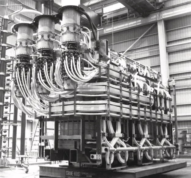
Load tap changers are typically sophisticated mechanical devices that can be remotely controlled. Tap changes can be made to occur automatically when the voltage levels drop below or rise above certain predetermined values. Maintaining nominal or expected voltage levels is highly desirable since much electrical equipment is designed to operate efficiently and sometimes only within a certain voltage range. This is particularly true for solid-state equipment. De-energized tap changing is usually performed manually. This type of tap changing can be useful if a utility changes its operating voltage level at one location or if a transformer is moved to a different location where the operating voltage is slightly different. Thus, it is done infrequently. Figure 1.4 shows three load tap changers and their connections to three windings of a power transformer. The same transformer can be equipped with both types of tap changers.
FIGURE 1.4 Three load tap changers attached to three windings of a power transformer. These tap changers were made by the Maschinenfabrik Reinhausen Co., Germany.
Most power systems today are 3-phase systems, that is, they produce sinusoidal voltages and currents in three separate lines or circuits with the sinusoids displaced in time relative to each other by 1/3 of a cycle or 120 electrical degrees as shown in Figure 1.5. At any instant of time, the three voltages sum to zero. Such a system made possible the use of generators and motors without commutators, which were cheaper and safer to operate. Thus, transformers that transformed all three phase voltages were required. This could be accomplished by using three separate transformers, one for each phase, or more commonly by combining all three phases within a single unit, permitting some economies particularly in the core structure. A sketch of such a unit is shown in Figure 1.6. Note that the three fluxes produced by the different phases are, like the voltages and currents, displaced in time by 1/3 of a cycle relative to each other. This means that, when they overlap in t...