Distribution System Modeling and Analysis
eBook - ePub

Distribution System Modeling and Analysis

William H. Kersting

Buch teilen
  1. 526 Seiten
  2. English
  3. ePUB (handyfreundlich)
  4. Über iOS und Android verfügbar
eBook - ePub

Distribution System Modeling and Analysis

William H. Kersting

Angaben zum Buch
Buchvorschau
Inhaltsverzeichnis
Quellenangaben

Über dieses Buch

The latest edition includes new sections on grounded wye–delta short circuit feedback current and simulation of loop flow. The text illustrates methods that ensure the most accurate results in computational modeling for electric power distribution systems. It clearly explains the principles and mathematics behind system models and discusses the "smart grid" concept and its special benefits. Including numerous models of components and several practical examples, the chapters demonstrate how engineers can apply and customize computer programs to help them plan and operate systems. The book also covers approximation methods to help users interpret computer program results, and includes references and assignments that help users apply Mathcad and WindMil programs to put their new learning into practice.

Häufig gestellte Fragen

Wie kann ich mein Abo kündigen?
Gehe einfach zum Kontobereich in den Einstellungen und klicke auf „Abo kündigen“ – ganz einfach. Nachdem du gekündigt hast, bleibt deine Mitgliedschaft für den verbleibenden Abozeitraum, den du bereits bezahlt hast, aktiv. Mehr Informationen hier.
(Wie) Kann ich Bücher herunterladen?
Derzeit stehen all unsere auf Mobilgeräte reagierenden ePub-Bücher zum Download über die App zur Verfügung. Die meisten unserer PDFs stehen ebenfalls zum Download bereit; wir arbeiten daran, auch die übrigen PDFs zum Download anzubieten, bei denen dies aktuell noch nicht möglich ist. Weitere Informationen hier.
Welcher Unterschied besteht bei den Preisen zwischen den Aboplänen?
Mit beiden Aboplänen erhältst du vollen Zugang zur Bibliothek und allen Funktionen von Perlego. Die einzigen Unterschiede bestehen im Preis und dem Abozeitraum: Mit dem Jahresabo sparst du auf 12 Monate gerechnet im Vergleich zum Monatsabo rund 30 %.
Was ist Perlego?
Wir sind ein Online-Abodienst für Lehrbücher, bei dem du für weniger als den Preis eines einzelnen Buches pro Monat Zugang zu einer ganzen Online-Bibliothek erhältst. Mit über 1 Million Büchern zu über 1.000 verschiedenen Themen haben wir bestimmt alles, was du brauchst! Weitere Informationen hier.
Unterstützt Perlego Text-zu-Sprache?
Achte auf das Symbol zum Vorlesen in deinem nächsten Buch, um zu sehen, ob du es dir auch anhören kannst. Bei diesem Tool wird dir Text laut vorgelesen, wobei der Text beim Vorlesen auch grafisch hervorgehoben wird. Du kannst das Vorlesen jederzeit anhalten, beschleunigen und verlangsamen. Weitere Informationen hier.
Ist Distribution System Modeling and Analysis als Online-PDF/ePub verfügbar?
Ja, du hast Zugang zu Distribution System Modeling and Analysis von William H. Kersting im PDF- und/oder ePub-Format sowie zu anderen beliebten Büchern aus Technology & Engineering & Electrical Engineering & Telecommunications. Aus unserem Katalog stehen dir über 1 Million Bücher zur Verfügung.

Information

1
Introduction to Distribution Systems

The major components of an electric power system are shown in Figure 1.1. Of these components, the distribution system has traditionally been characterized as the most unglamorous component. In the latter half of the 20th century, the design and operation of the generation and transmission components presented many challenges to the practicing engineers and researchers. Power plants became larger, and transmission lines crisscrossed the land, forming large interconnected networks. The operation of the large interconnected networks required the development of new analysis and operational techniques. Meanwhile, the distribution systems continued to deliver power to the ultimate user’s meter with little or no analysis. As a direct result, distribution systems were typically over-designed.
Nowadays, it has become very important and necessary to operate a distribution system at its maximum capacity. Some of the questions that need to be answered are as follows:
  1. What is the maximum capacity?
  2. How do we determine this capacity?
  3. What are the operating limits that must be satisfied?
  4. What can be done to operate the distribution system within the operating limits?
  5. What can be done to make the distribution system operate more efficiently?
All of these questions can be answered only if the distribution system is modeled very accurately.
The purpose of this text is to develop accurate models for all of the major components of a distribution system. Once the models have been developed, analysis techniques for steady-state and short-circuit conditions will be developed.

1.1 The Distribution System

The distribution system typically starts with the distribution substation that is fed by one or more subtransmission lines. In some cases, the distribution substation is fed directly from a high-voltage transmission line in which case, most likely, there is no subtransmission system. This varies from company to company. Each distribution substation will serve one or more primary feeders. With a rare exception, the feeders are radial, which means that there is only one path for power to flow from the distribution substation to the user.
images
FIGURE 1.1
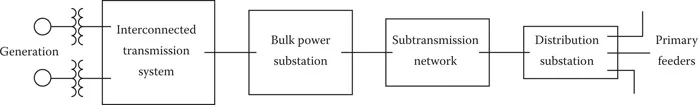
Major power system components.

1.2 Distribution Substations

A one-line diagram of a very simple distribution substation is shown in Figure 1.2.
Although Figure 1.2 displays the simplest of distribution substations, it does illustrate the major components that will be found in all substations.
  1. High-side and low-side switching: In Figure 1.2, the high-voltage switching is done with a simple switch. Substations that are more extensive may use high-voltage circuit breakers (CBs) in a variety of high-voltage bus designs. The low-voltage switching in Figure 1.2 is accomplished with relay-controlled CBs. In many cases, reclosers will be used in place of the relay–CB combination. Some substation designs include a low-voltage bus CB in addition to the CBs for each feeder. As is the case with the high-voltage bus, the low-voltage bus can take on a variety of designs.
  2. Voltage transformation: The primary function of a distribution substation is to reduce the voltage down to the distribution voltage level. In Figure 1.2, only one transformer is shown. Other substation designs will call for two or more three-phase transformers. The substation transformers can be three-phase units or three single-phase units connected in a standard connection. There are many “standard” distribution voltage levels. Some of the common ones are 34.5, 23.9, 14.4, 13.2, 12.47 kV, and, in older systems, 4.16 kV.
  3. Voltage regulation: Because the load on the feeders vary, the voltage drop between the substation and the user will vary. In order to maintain the user’s voltages within an acceptable range, the voltage at the substation needs to vary as the load varies. In Figure 1.2, the voltage is regulated by a “step-type” regulator that will vary the voltage plus or minus 10% on the low-side bus. Sometimes this function is accomplished with a “load tap changing” (LTC) transformer. The LTC changes the taps on the low-voltage windings of the transformer as the load varies. Many substation transformers will have “fixed taps” on the high-voltage winding. These are used when the source voltage is always either above or below the nominal voltage. The fixed tap settings can vary the voltage plus or minus 5%. Mostly, instead of a bus regulator, each feeder will have its own regulator. This can be in the form of a three-phase gang-operated regulator or individual phase regulators that operate independently.
  4. Protection: The substation must be protected against the occurrence of short circuits. In the simple design in Figure 1.2, the only automatic protection against short circuits inside the substation is by way of the high-side fuses on the transformer. As the substation designs become more complex, more extensive protective schemes will be employed to protect the transformer, the high- and low-voltage buses, and any other piece of equipment. Individual feeder CBs or reclosers are used to provide interruption of short circuits that occur outside the substation.
  5. Metering: Every substation has some form of metering. This may be as simple as an analog ammeter displaying the present value of substation current as well as the minimum and maximum currents that have occurred over a specific time period. Digital recording meters are becoming very common. These meters record the minimum, average, and maximum values of current, voltage, power, power factor, etc., over a specified time range. Typical time ranges are 15 min, 30 min, and 1 h. The digital meters may monitor the output of each substation transformer and/or the output of each feeder.
images
FIGURE 1.2
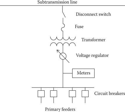
Simple distribution substation.
A more comprehensive substation layout is shown in Figure 1.3.
The substation in Figure 1.3 has two LTC transformers, serves four distribution feeders, and is fed from two substransmission lines. Under normal conditions, the CBs are in the following positions:
  1. Circuit breakers closed: X, Y, 1, 3, 4, 6
  2. Circuit breakers open: Z, 2, 5
With the breakers in their normal positions, each transformer is served from a different subtransmission line and serves two feeders. If one of the subtransmission lines goes out of service, then breaker X or Y is opened and breaker Z is closed. Now both transformers are served from the same subtransmission line. The transformers are sized such that each transformer can supply all four feeders under an emergency operating condition. For example, if transformer T-1 is out of service, then breakers X, 1, and 4 are opened and breakers 2 and 5 are closed. With that ...

Inhaltsverzeichnis