
eBook - ePub
Marine Propellers and Propulsion
John Carlton
This is a test
Buch teilen
- 609 Seiten
- English
- ePUB (handyfreundlich)
- Über iOS und Android verfügbar
eBook - ePub
Marine Propellers and Propulsion
John Carlton
Angaben zum Buch
Buchvorschau
Inhaltsverzeichnis
Quellenangaben
Über dieses Buch
Marine Propellers and Propulsion, Fourth Edition, offers comprehensive, cutting edge coverage to equip marine engineers, naval architects or anyone involved in propulsion and hydrodynamics with essential job knowledge. Propulsion technology is a complex, multidisciplinary topic with design, construction, operational and research implications. Drawing on experience from a long and varied career in consulting, research, design and technical investigation, John Carlton examines hydrodynamic theory, materials and mechanical considerations, and design, operation and performance. Connecting essential theory to practical problems in design, analysis and operational efficiency, the book is an invaluable resource, packed with hard-won insights, detailed specifications and data.
- Features comprehensive coverage of marine propellers, fully updated and revised, with new chapters on propulsion in ice and high speed propellers
- Includes enhanced content on full-scale trials, propeller materials, propeller blade vibration, operational problems and much more
- Synthesizes otherwise disparate material on the theory and practice of propulsion technology from the past 40 years' development, including the latest developments in improving efficiency
- Written by a leading expert on propeller technology, essential for students, marine engineers and naval architects involved in propulsion and hydrodynamics
Häufig gestellte Fragen
Wie kann ich mein Abo kündigen?
Gehe einfach zum Kontobereich in den Einstellungen und klicke auf „Abo kündigen“ – ganz einfach. Nachdem du gekündigt hast, bleibt deine Mitgliedschaft für den verbleibenden Abozeitraum, den du bereits bezahlt hast, aktiv. Mehr Informationen hier.
(Wie) Kann ich Bücher herunterladen?
Derzeit stehen all unsere auf Mobilgeräte reagierenden ePub-Bücher zum Download über die App zur Verfügung. Die meisten unserer PDFs stehen ebenfalls zum Download bereit; wir arbeiten daran, auch die übrigen PDFs zum Download anzubieten, bei denen dies aktuell noch nicht möglich ist. Weitere Informationen hier.
Welcher Unterschied besteht bei den Preisen zwischen den Aboplänen?
Mit beiden Aboplänen erhältst du vollen Zugang zur Bibliothek und allen Funktionen von Perlego. Die einzigen Unterschiede bestehen im Preis und dem Abozeitraum: Mit dem Jahresabo sparst du auf 12 Monate gerechnet im Vergleich zum Monatsabo rund 30 %.
Was ist Perlego?
Wir sind ein Online-Abodienst für Lehrbücher, bei dem du für weniger als den Preis eines einzelnen Buches pro Monat Zugang zu einer ganzen Online-Bibliothek erhältst. Mit über 1 Million Büchern zu über 1.000 verschiedenen Themen haben wir bestimmt alles, was du brauchst! Weitere Informationen hier.
Unterstützt Perlego Text-zu-Sprache?
Achte auf das Symbol zum Vorlesen in deinem nächsten Buch, um zu sehen, ob du es dir auch anhören kannst. Bei diesem Tool wird dir Text laut vorgelesen, wobei der Text beim Vorlesen auch grafisch hervorgehoben wird. Du kannst das Vorlesen jederzeit anhalten, beschleunigen und verlangsamen. Weitere Informationen hier.
Ist Marine Propellers and Propulsion als Online-PDF/ePub verfügbar?
Ja, du hast Zugang zu Marine Propellers and Propulsion von John Carlton im PDF- und/oder ePub-Format sowie zu anderen beliebten Büchern aus Technology & Engineering & Mechanical Engineering. Aus unserem Katalog stehen dir über 1 Million Bücher zur Verfügung.
Information
Chapter 1
The Early Development of the Screw Propeller
Abstract
Both Archimedes (c.250 BC) and Leonardo da Vinci (c.1500) can be credited with having considered designs and ideas, which would subsequently be explored by ship propulsion engineers many years later. In the case of Archimedes, his thoughts centered on the application of the screw pump, which bears his name and this provided inspiration to the 19th-century engineers involved in marine propulsion. Unfortunately, however, it also gave rise to several subsequent misconceptions about the basis of propeller action by comparing it to that of a screw thread. In contrast Leonardo da Vinci, in his sketchbooks, which were produced some 1700 years after Archimedes, shows an alternative form of screw propulsion based on the idea of using fan blades, which had a similar appearance to those used for cooling purposes today.
Keywords
Propeller; Screw; Propulsion; Development; Design; Marine
Both Archimedes (c.250 BC) and Leonardo da Vinci (c.1500) can be credited with having considered designs and ideas, which would subsequently be explored by ship propulsion engineers many years later. In the case of Archimedes, his thoughts centered on the application of the screw pump, which bears his name and this provided inspiration to the 19th-century engineers involved in marine propulsion. Unfortunately, however, it also gave rise to several subsequent misconceptions about the basis of propeller action by comparing it to that of a screw thread. In contrast Leonardo da Vinci, in his sketchbooks, which were produced some 1700 years after Archimedes, shows an alternative form of screw propulsion based on the idea of using fan blades, which had a similar appearance to those used for cooling purposes today.
The development of screw propulsion as we recognize it today can be traced back to the work of Robert Hooke who is perhaps better remembered for his work on the elasticity of materials. Hooke in his Philosophical Collections, presented to the Royal Society in 1681, explained the design of a horizontal watermill, which was remarkably similar in its principle of operation to the Kirsten-Boeing vertical axis propeller developed two and a half centuries later. Hooke’s watermill comprised six wooden vanes, geared to a central shaft and pinned vertically to a horizontal circular rotor. The gearing constrained the vanes to rotate through 180 degrees about their own spindle axes for each complete revolution of the rotor.
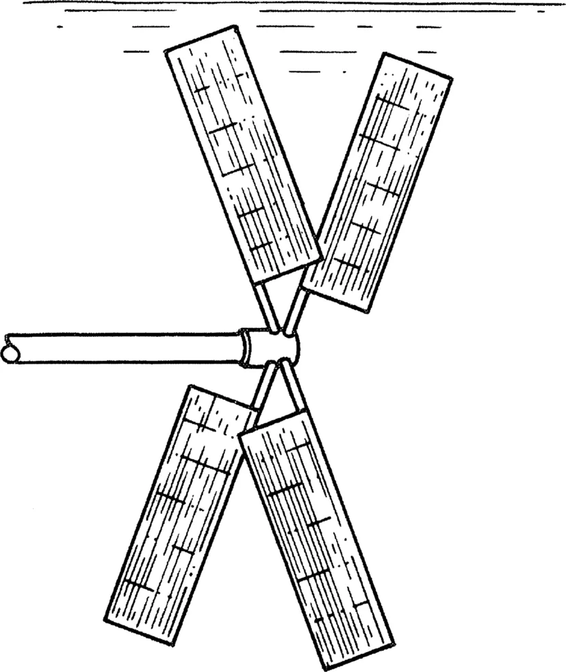
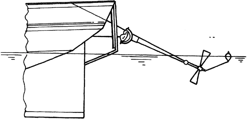
During his life, Hooke was also interested in the subject of metrology and in the course of his work he developed an air flow meter based on the principle of a windmill. He successfully modified this instrument in 1683 to measure water currents and then foresaw the potential of this invention to propel ships if provided with a suitable means of motive power. As seen from Fig. 1.1 the instrument comprised four, flat rectangular blades located on radial arms with the blades inclined to the plane of rotation.
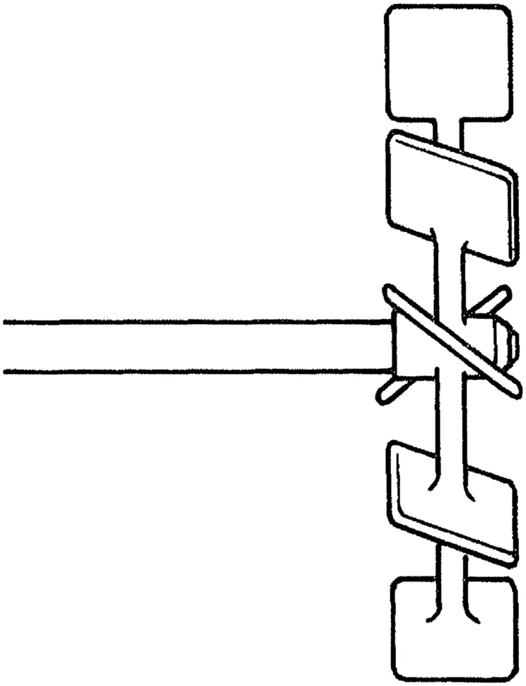
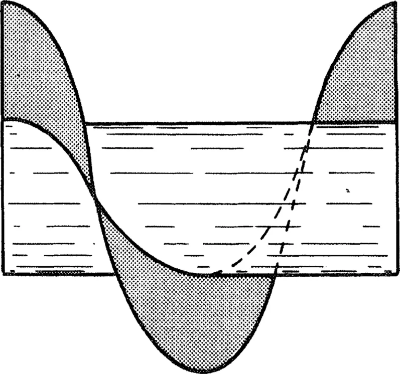
Some years later in 1752, the Académie des Sciences in Paris offered a series of prizes for research into theoretical methods leading to significant developments in naval architecture. As might be expected, many of the famous mathematicians and scientists of Europe were attracted by this offer and names such as d’Alembert, Euler, and Bernoulli appear in the contributions. Bernoulli’s contribution, for which he won a prize, introduced the propeller wheel, shown in Fig. 1.2, which he intended to be driven by a Newcomen steam engine. With this arrangement, he calculated that a particular ship could be propelled at just under 2½ knots by the application of some 20–25 hp. Opinion, however, was still divided as to the most suitable propulsor configuration: indeed, as it was to be for many years to come. For example, the French mathematician Paucton, working at about the same time as Bernoulli, suggested a different approach, illustrated in Fig. 1.3, which was based on the Archimedean screw principle.
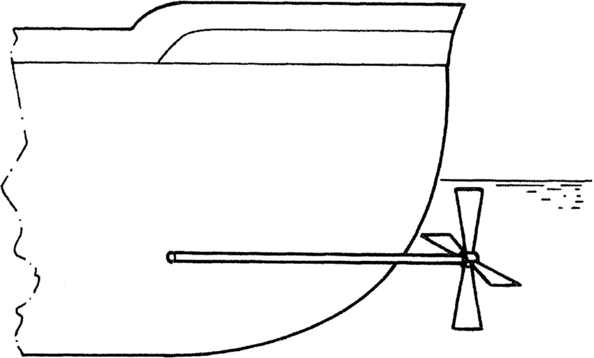
Thirty-three years after the Paris invitation Joseph Bramah in England proposed an arrangement for a screw propeller located at the stern of a vessel, which, as is seen from Fig. 1.4, contains most of the features, which we associate with screw propulsion today. It comprised a propeller with a small number of blades driven by a horizontal shaft, which passes into the ship’s hull below the waterline. However, there appears to be no evidence of any trials of a propeller of this kind being fitted to a ship and driven by a steam engine. Nevertheless, in 1802, Edward Shorter used a variation of Bramah’s idea to assist sailing vessels that were becalmed to make some headway. In Shorter’s proposal, Fig. 1.5, the shaft was designed to pass into the vessel’s hull above the waterline, which eliminated the need for seals, and the motive power for this propulsion arrangement was provided by eight men turning a capstan. Using this technique, Shorter managed to propel the transport ship Doncaster in Gibraltar and again at Malta at a speed of 1.5 mph in calm conditions. Perhaps in view of the means of providing the motive power no further application of Shorter’s propeller was recorded. Nevertheless, it is interesting to note the enthusiasm with which this propeller was received by Admiral Sir Richard Rickerton and his Captains as witnessed by the transcript of a letter dated the 4th July 1802; Fig. 1.6. However, Edward Shorter recognized that this propulsion concept could be driven by a steam engine.

Colonel John Stevens, who was a lawyer in the United States and a man of substantial financial means, experimented with screw propulsion in the year following Edward Shorter’s proposal. As a basis for his work, he built a 25-ft long boat into which he installed a rotary steam engine and coupled this directly to a four-bladed propeller. The blades of this propeller were flat iron plates riveted to forgings, which formed a “spider-like” boss attachment to the shaft. Stevens later replaced the rotary engine with a steam engine of the Watt type and managed to attain a steady cruising speed of 4 mph with some occasional surges of up to 8 mph. However, he was not impressed with the overall performance of his craft and decided to turn his attention and energies to other forms of marine propulsion.
In 1824 contrarotating propellers made their appearance in France in a design produced by Monsieur Dollman. He used a pair of two-bladed windmill type propellers rotating in opposite directions on the same shaft axis to propel a small craft. Following on from this French development, the scene turned once again to England where John Ericsson, a former Swedish army officer residing at that time in London, designed and patented in 1836 a propulsion system comprising two contrarotating propeller wheels. His design is shown in Fig. 1.7, from which it can be seen that the individual wheels were not dissimilar in outline to Bernoulli’s earlier proposal. Each wheel comprised eight short, wide blades of a helical configuration mounted on a blade ring with the blades tied at their tips by a peripheral strap. In this arrangement, the two wheels were allowed to rotate at different speeds, probably to overcome the problem of the different flow configurations induced in the forward and after wheels and, perhaps, also blade passing frequency issues. Ericsson conducted his early trials on a 3-ft model and the results proved successful enough to encourage him to construct a 45-ft vessel, which he named the Francis B. Ogden. This vessel was fitted with his propulsion system, which had blade wheels having a diameter of 5 ft 2 in. Trials were conducted on the River Thames in the presence of representatives from the Admiralty and the vessel was observed to be capable of a speed of some 10 mph. However, in his first design, Ericsson placed the propeller astern of the rudder and this had an adverse effect both on the steering characteristics of the ship and on the water flow into the propeller. The Admiralty Board expressed disappointment with the trial, although the propulsion results were good when judged by the standards of the day. It was said that one reason for their concern was over a vessel’s ability to steer reliably when propelled from the stern. Following this rebuff, Ericsson left England for the United States and in 1843 designed the US Navy’s first screw-propelled vessel, the Princeton. It has subsequently been suggested that by around this time the US merchant marine had some 41 screw-propelled vessels in operation.

The development of the screw propeller depended not only on technical development but also upon the availability of finance as well as being subjected to political influences and the likely return on the initial investment that might accrue to the inventor or his backers. Francis Petit Smith was rather more successful in these respects than his contemporary Ericsson. Smith took out a patent in which a different form of propeller was used, more akin to an Archimedean screw, but, more importantly, based on a different location of the propeller with respect to the rudder. This happened just a few weeks prior to Ericsson establishing his patent and shortly after Ericsson’s trials the British Admiralty modified their view of screw propulsion due to Smith’s work.
Despite being frequently referred to as a farmer, Smith had a sound classical education and explored the concepts of marine propulsion by making model boats and testing them on a pond. From one such model, which was propelled by an Archimedean screw, he was sufficiently encouraged to build a 6-ton prototype boat, the F P Smith. This was powered by a 6-hp steam engine and to which he fitted a wooden Archimedean screw of two turns and the vessel underwent trials on the Paddington Canal in 1837. However, by one of those fortunate accidents, which sometimes occur in the history of science and technology, the propeller was damaged during the trials and about half of it broke off, whereupon the vessel immediately increased its speed. Smith recognized the implications of this accident and modified the propeller accordingly. After completing calm water trials, he took the vessel on a voyage down the River Thames from Blackwall in a series of stages to Folkestone and then eventually on to Hythe on the Kentish coast. Between these last two ports the vessel averaged a speed of some 7 mph. On the return voyage to London, Smith encountered a storm in the Thames Estuary and the little craft apparently performed excellently in these adverse weather conditions. In March 1830 Smith and his backers, Wright and the Rennie brothers, made an approach to the Admiralty, wh...