
eBook - ePub
Principles of Fluoroscopic Image Intensification and Television Systems
Workbook and Laboratory Manual
Robert J. Parelli
This is a test
Buch teilen
- 252 Seiten
- English
- ePUB (handyfreundlich)
- Über iOS und Android verfügbar
eBook - ePub
Principles of Fluoroscopic Image Intensification and Television Systems
Workbook and Laboratory Manual
Robert J. Parelli
Angaben zum Buch
Buchvorschau
Inhaltsverzeichnis
Quellenangaben
Über dieses Buch
This unique workbook can be used as a stand-alone text or supplemental text for any course designed to enhance the work of radiologic technology students. It will also serve the needs of graduate radiographers as well as the physician in learning specific areas of the Fluoroscopic Image Intensifier such as:
Häufig gestellte Fragen
Wie kann ich mein Abo kündigen?
Gehe einfach zum Kontobereich in den Einstellungen und klicke auf „Abo kündigen“ – ganz einfach. Nachdem du gekündigt hast, bleibt deine Mitgliedschaft für den verbleibenden Abozeitraum, den du bereits bezahlt hast, aktiv. Mehr Informationen hier.
(Wie) Kann ich Bücher herunterladen?
Derzeit stehen all unsere auf Mobilgeräte reagierenden ePub-Bücher zum Download über die App zur Verfügung. Die meisten unserer PDFs stehen ebenfalls zum Download bereit; wir arbeiten daran, auch die übrigen PDFs zum Download anzubieten, bei denen dies aktuell noch nicht möglich ist. Weitere Informationen hier.
Welcher Unterschied besteht bei den Preisen zwischen den Aboplänen?
Mit beiden Aboplänen erhältst du vollen Zugang zur Bibliothek und allen Funktionen von Perlego. Die einzigen Unterschiede bestehen im Preis und dem Abozeitraum: Mit dem Jahresabo sparst du auf 12 Monate gerechnet im Vergleich zum Monatsabo rund 30 %.
Was ist Perlego?
Wir sind ein Online-Abodienst für Lehrbücher, bei dem du für weniger als den Preis eines einzelnen Buches pro Monat Zugang zu einer ganzen Online-Bibliothek erhältst. Mit über 1 Million Büchern zu über 1.000 verschiedenen Themen haben wir bestimmt alles, was du brauchst! Weitere Informationen hier.
Unterstützt Perlego Text-zu-Sprache?
Achte auf das Symbol zum Vorlesen in deinem nächsten Buch, um zu sehen, ob du es dir auch anhören kannst. Bei diesem Tool wird dir Text laut vorgelesen, wobei der Text beim Vorlesen auch grafisch hervorgehoben wird. Du kannst das Vorlesen jederzeit anhalten, beschleunigen und verlangsamen. Weitere Informationen hier.
Ist Principles of Fluoroscopic Image Intensification and Television Systems als Online-PDF/ePub verfügbar?
Ja, du hast Zugang zu Principles of Fluoroscopic Image Intensification and Television Systems von Robert J. Parelli im PDF- und/oder ePub-Format sowie zu anderen beliebten Büchern aus Law & Forensic Science. Aus unserem Katalog stehen dir über 1 Million Bücher zur Verfügung.
Information
Chapter 1
Image Intensifier System
Objectives
Upon completion of Chapter 1, the reader will be able to:
1. Describe the basic parts of the image intensifier tube: input phosphor and photocathode, electrostatic lens, accelerating anode, and output phosphor.
2. Explain how to use a dual field image intensifier tube for magnification procedures.
3. Calculate the amount of patient exposure in the magnified mode.
4. Define conversion factor and brightness gain.
5. Calculate the minification ratio of the image intensifier tube.
6. Explain how image quality of the image intensifier tube is affected by scintillation, resolution, contrast, and distortion.
7. Describe the automatic brightness stabilizer system.
8. Recall the types of brightness sensing devices.
9. Identify the types of automatic brightness sensing circuits that are used with the x-ray generator.
Conventional fluoroscopy, without image intensification, has two serious limitations: it produces a statistically inferior image and one too dim for photopic (daylight) vision. In the early 1950s, the x-ray image intensifier was developed, which has revolutionized fluoroscopy. Its image is bright enough for scotopic vision and small enough to be conveniently coupled to cine, television, or spot-film cameras.
Image Intensifier Tube Design
The image intensifier tube is an evacuated glass envelope, a vacuum tube, which contains four basic parts (Figure 1.1):
1. Input phosphor and photocathode.
2. Electrostatic focusing lens.
3. Accelerating anode.
4. Output phosphor.
Input Phosphor and Photocathode
First-generation image intensifier tubes had silver-activated zinc cadmium sulfide crystals in the input screen. Second-generation intensifiers have cesium iodide (Csl) input screens. The fluorescent material is deposited on a thin substrate of the glass envelope. It serves the purpose of converting incident x-ray beam photons into a light image. The fluorescent screen and the photocathode are separated by a thin transparent layer only a fraction of a millimeter. Very little of the image is lost as the image is transferred from the screen to the photocathode.

The photocathode is a photo-emissive metal (usually a combination of antimony [Sb] and cesium [Cs] compounds). The photocathode receives the light emitted from the input screen and emits electrons in proportion to the intensity of the light it receives. One can appreciate the necessity of the input screen and photocathode being in very close proximity. Otherwise the image detail transmitted from one to the other would be significantly degraded. The photocathode also serves as the cathode of the image intensifier tube. It is kept at ground potential. By establishing a voltage or difference in electrical potential between the cathode and the accelerating anode, the electrons can be made to transverse the tube toward the output screen.
Electrostatic Focusing Lens
The focusing of electrons is accomplished by a series of rings called the electrostatic lenses, which are located inside the tube envelope and concentric with the tube axis. Applying a positive electrical potential difference to the electrostatic lens will cause the electrons emitted from the photocathode to be focused into an extremely fine beam. Each point on the input screen is focused to a specific point on the opposite side of the output screen. Electron focusing inverts the image on the output phosphor. The image on the output phosphor is reduced in size, which is one of the principal reasons why it is brighter.
Accelerating Anode
Located at the neck of the image intensifier tube, the accelerating anode draws electrons from the photocathode and accelerates them toward the output screen. The anode of a 6-in. image intensifier tube has a positive potential difference (voltage) of 25,000 volts (25 kVp), so it accelerates electrons to a tremendous velocity.
Output Phosphor
The output fluorescent screen of the 6-in. image intensifier tube is made from cesium iodide. The crystal size and layer thickness are reduced to maintain resolution in the minified image. Since the electrons are greatly accelerated, they emit more light photons from the output screen than were originally present in the input screen. The number of light photons is increased approximately 50 times. A thin layer of aluminum is plated onto the fluorescent screen to prevent light from moving retrograde through the tube and activating the photocathode. The aluminum layer is very thin, and high-energy photoelectrons easily pass through it en route to the output screen. This layer also serves as a ground to remove spent electrons from the image tube. If they were not removed, they would accumulate on the output phosphor and build up a negative charge.
The output screen is optically coupled to a viewing system by subjective lenses. The image is viewed either directly through a series of lenses and mirrors or indirectly through a closed circuit television system.
Dual Field Image Intensifier Tubes
Field size on the output phosphor is changed by applying a simple electronic principle: the higher the voltage on the electrostatic focusing lens, the more the electron beam is focused. Figure 1.2 shows this principle applied to a dual field image intensifier.
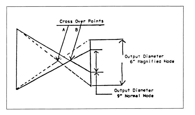
In the 9-in. mode, the electrostatic focusing voltage is decreased. The electrons focus to a point, or cross, close to the output phosphor, and the image is actually smaller than the phosphor. In the 6-in. mode, the electrostatic focusing voltage is increased, and the electrons focus farther away from the output phosphor. After the electrons cross, they diverge so the image on the output screen is larger than the 9-in. mode. The physical size of the input and output screens is the same in both modes; the only thing that changes is the size of the output image. Therefore, the 6- and 9-in. modes have different minification gains. Exposure factors are automatically increased when the unit is used in the magnified mode to compensate for the decreased brightness from minification. The ratio of patient exposure is calculated using this formula:
Example: When operating the image intensifier in the magnified 6-in. mode from the normal 9-in. mode, the patient will receive how many times more exposure?
Answer:
It is important to note that the normal mode is always used to view larger anatomic areas with less patient exposure. When size is unimportant, the magnified mode is used for better resultant image quality. The mA is automatically increased when the unit is used in the 6-in. magnified mode to compensate for the decreased brightness. Therefore, patient dose is increased.
Conversion Factor and Gain
When x-ray image intensifier tubes were first introduced, some means was needed to express their increased intensity. Because of the past familiarity with conventional fluoroscopic screens, it became commonplace to compare the image intensifier tube to the screen. The brightness gain, or “intensification gain” as it was called, was then expressed as the luminance of the output screen compared to the luminance of a standard Patterson fluoroscopic screen with the same incident radiation. The brightness gain is the ratio of the two illuminations:
The first image tubes that gained widespread acceptance had gains on the order of 3,000 or possibly a little higher. As improvements in design and manufacturing came along, this gain grad...