
eBook - ePub
Surface Production Operations, Volume 1
Design of Oil Handling Systems and Facilities
Maurice Stewart, Ken E. Arnold
This is a test
Compartir libro
- 768 páginas
- English
- ePUB (apto para móviles)
- Disponible en iOS y Android
eBook - ePub
Surface Production Operations, Volume 1
Design of Oil Handling Systems and Facilities
Maurice Stewart, Ken E. Arnold
Detalles del libro
Vista previa del libro
Índice
Citas
Información del libro
The latest edition of this best-selling title is updated and expanded for easier use by engineers. New to this edition is a section on the fundamentals of surface production operations taking up topics from the oilfield as originally planned by the authors in the first edition. This information is necessary and endemic to production and process engineers. Now, the book offers a truly complete picture of surface production operations, from the production stage to the process stage with applications to process and production engineers.
- New in-depth coverage of hydrocarbon characteristics, the different kinds of reservoirs, and impurities in crude
- Practical suggestions help readers understand the art and science of handling produced liquids
- Numerous, easy-to-read figures, charts, tables, and photos clearly explain how to design, specify, and operate oilfield surface production facilities
Preguntas frecuentes
¿Cómo cancelo mi suscripción?
¿Cómo descargo los libros?
Por el momento, todos nuestros libros ePub adaptables a dispositivos móviles se pueden descargar a través de la aplicación. La mayor parte de nuestros PDF también se puede descargar y ya estamos trabajando para que el resto también sea descargable. Obtén más información aquí.
¿En qué se diferencian los planes de precios?
Ambos planes te permiten acceder por completo a la biblioteca y a todas las funciones de Perlego. Las únicas diferencias son el precio y el período de suscripción: con el plan anual ahorrarás en torno a un 30 % en comparación con 12 meses de un plan mensual.
¿Qué es Perlego?
Somos un servicio de suscripción de libros de texto en línea que te permite acceder a toda una biblioteca en línea por menos de lo que cuesta un libro al mes. Con más de un millón de libros sobre más de 1000 categorías, ¡tenemos todo lo que necesitas! Obtén más información aquí.
¿Perlego ofrece la función de texto a voz?
Busca el símbolo de lectura en voz alta en tu próximo libro para ver si puedes escucharlo. La herramienta de lectura en voz alta lee el texto en voz alta por ti, resaltando el texto a medida que se lee. Puedes pausarla, acelerarla y ralentizarla. Obtén más información aquí.
¿Es Surface Production Operations, Volume 1 un PDF/ePUB en línea?
Sí, puedes acceder a Surface Production Operations, Volume 1 de Maurice Stewart, Ken E. Arnold en formato PDF o ePUB, así como a otros libros populares de Technik & Maschinenbau y Chemie- & Biochemietechnik. Tenemos más de un millón de libros disponibles en nuestro catálogo para que explores.
Información
Chapter 1 The Production Facility
Introduction
The job of a production facility is to separate the well stream into three components, typically called “phases” (oil, gas, and water), and process these phases into some marketable product(s) or dispose of them in an environmentally acceptable manner. In mechanical devices called “separators,” gas is flashed from the liquids and “free water” is separated from the oil. These steps remove enough light hydrocarbons to produce a stable crude oil with the volatility (vapor pressure) to meet sales criteria. Figures 1-1 and 1-2 show typical separators used to separate gas from liquid or water from oil. Separators can be either horizontal or vertical in configuration. The gas that is separated must be compressed and treated for sales. Compression is typically done by engine-driven reciprocating compressors (see Figure 1-3). In large facilities or in booster service, turbine-driven centrifugal compressors, such as that shown in Figure 1-4, are used. Large integral reciprocating compressors are also used (see Figure 1-5).
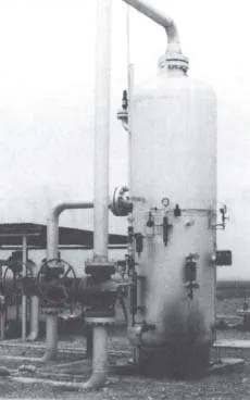
Figure 1-1. A typical vertical two phase separator at a land location. The inlet comes in the left side, gas comes off the top, and liquid leaves the bottom right side of the separator.
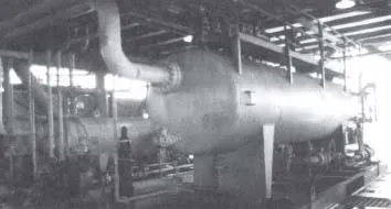
Figure 1-2. A typical horizontal separator on an offshore platform showing the inlet side. Note the drain valves at various points along the bottom and the access platform along the top.
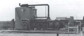
Figure 1-3. Engine-driven reciprocating compressor package. The inlet and inter-stage scrubbers (separators) are at the right. The gas is routed through pulsation bottles to gas cylinders and then to the cooler on the left end of the package. The engine that drives the compressor cylinders is located to the right of the box-like cooler.
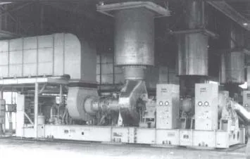
Figure 1-4. Turbine-driven centrifugal compressor package. The turbine draws air in from the large duct on the left. This is mixed with fuel and ignited. The jet of gas thus created causes the turbine blades to turn at high speed before being exhausted vertically upward through the large cylindrical duct. The turbine shaft drives the two centrifugal compressors, which are located behind the control cabinets on the tight end of the skid.
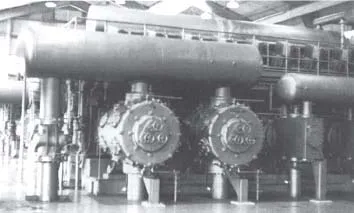
Figure 1-5. A 5500-Bhp integral reciprocating compressor. The sixteen power cylinders located at the top of the unit (eight on each side) drive a crankshaft that is directly coupled to the horizontal compressor cylinders facing the camera. Large cylindrical “bottles” mounted above and below the compressor cylinders filter out acoustical pulsations in the gas being compressed.
Usually, the separated gas is saturated with water vapor and must be dehydrated to an acceptable level, normally less than 7 lb/MMscf (110 mg H2O/Sm3). This is normally done in a glycol dehydrator, such as that shown in Figure 1-6.
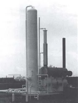
Figure 1-6. A small glycol gas dehydration system. The large vertical vessel on the left is the contact tower where “dry” glycol contacts the gas and absorbs water vapor. The upper horizontal vessel is the “reboiler” or “reconcentrator” where the wet glycol is heated, boiling off the water that exits the vertical pipe coming off the top just behind the contact tower. The lower horizontal vessel serves as a surge tank.
Dry glycol is pumped to the large vertical contact tower, where it strips the gas of its water vapor. The wet glycol then flows through a separator to the large horizontal reboiler, where it is heated and the water boiled off as steam.
In some locations it may be necessary to remove the heavier hydrocarbons to lower the hydrocarbon dew point. Contaminants such as H2S and CO2 may be present at levels higher than those acceptable to the gas purchaser. If this is the case, then additional equipment will be necessary to “sweeten” the gas.
The oil and emulsion from the separators must be treated to remove water. Most oil contracts specify a maximum perce...