
eBook - ePub
Surface Production Operations, Volume 1
Design of Oil Handling Systems and Facilities
Maurice Stewart, Ken E. Arnold
This is a test
Partager le livre
- 768 pages
- English
- ePUB (adapté aux mobiles)
- Disponible sur iOS et Android
eBook - ePub
Surface Production Operations, Volume 1
Design of Oil Handling Systems and Facilities
Maurice Stewart, Ken E. Arnold
Détails du livre
Aperçu du livre
Table des matières
Citations
À propos de ce livre
The latest edition of this best-selling title is updated and expanded for easier use by engineers. New to this edition is a section on the fundamentals of surface production operations taking up topics from the oilfield as originally planned by the authors in the first edition. This information is necessary and endemic to production and process engineers. Now, the book offers a truly complete picture of surface production operations, from the production stage to the process stage with applications to process and production engineers.
- New in-depth coverage of hydrocarbon characteristics, the different kinds of reservoirs, and impurities in crude
- Practical suggestions help readers understand the art and science of handling produced liquids
- Numerous, easy-to-read figures, charts, tables, and photos clearly explain how to design, specify, and operate oilfield surface production facilities
Foire aux questions
Comment puis-je résilier mon abonnement ?
Il vous suffit de vous rendre dans la section compte dans paramètres et de cliquer sur « Résilier l’abonnement ». C’est aussi simple que cela ! Une fois que vous aurez résilié votre abonnement, il restera actif pour le reste de la période pour laquelle vous avez payé. Découvrez-en plus ici.
Puis-je / comment puis-je télécharger des livres ?
Pour le moment, tous nos livres en format ePub adaptés aux mobiles peuvent être téléchargés via l’application. La plupart de nos PDF sont également disponibles en téléchargement et les autres seront téléchargeables très prochainement. Découvrez-en plus ici.
Quelle est la différence entre les formules tarifaires ?
Les deux abonnements vous donnent un accès complet à la bibliothèque et à toutes les fonctionnalités de Perlego. Les seules différences sont les tarifs ainsi que la période d’abonnement : avec l’abonnement annuel, vous économiserez environ 30 % par rapport à 12 mois d’abonnement mensuel.
Qu’est-ce que Perlego ?
Nous sommes un service d’abonnement à des ouvrages universitaires en ligne, où vous pouvez accéder à toute une bibliothèque pour un prix inférieur à celui d’un seul livre par mois. Avec plus d’un million de livres sur plus de 1 000 sujets, nous avons ce qu’il vous faut ! Découvrez-en plus ici.
Prenez-vous en charge la synthèse vocale ?
Recherchez le symbole Écouter sur votre prochain livre pour voir si vous pouvez l’écouter. L’outil Écouter lit le texte à haute voix pour vous, en surlignant le passage qui est en cours de lecture. Vous pouvez le mettre sur pause, l’accélérer ou le ralentir. Découvrez-en plus ici.
Est-ce que Surface Production Operations, Volume 1 est un PDF/ePUB en ligne ?
Oui, vous pouvez accéder à Surface Production Operations, Volume 1 par Maurice Stewart, Ken E. Arnold en format PDF et/ou ePUB ainsi qu’à d’autres livres populaires dans Technik & Maschinenbau et Chemie- & Biochemietechnik. Nous disposons de plus d’un million d’ouvrages à découvrir dans notre catalogue.
Informations
Chapter 1 The Production Facility
Introduction
The job of a production facility is to separate the well stream into three components, typically called “phases” (oil, gas, and water), and process these phases into some marketable product(s) or dispose of them in an environmentally acceptable manner. In mechanical devices called “separators,” gas is flashed from the liquids and “free water” is separated from the oil. These steps remove enough light hydrocarbons to produce a stable crude oil with the volatility (vapor pressure) to meet sales criteria. Figures 1-1 and 1-2 show typical separators used to separate gas from liquid or water from oil. Separators can be either horizontal or vertical in configuration. The gas that is separated must be compressed and treated for sales. Compression is typically done by engine-driven reciprocating compressors (see Figure 1-3). In large facilities or in booster service, turbine-driven centrifugal compressors, such as that shown in Figure 1-4, are used. Large integral reciprocating compressors are also used (see Figure 1-5).
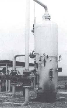
Figure 1-1. A typical vertical two phase separator at a land location. The inlet comes in the left side, gas comes off the top, and liquid leaves the bottom right side of the separator.
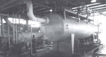
Figure 1-2. A typical horizontal separator on an offshore platform showing the inlet side. Note the drain valves at various points along the bottom and the access platform along the top.
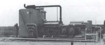
Figure 1-3. Engine-driven reciprocating compressor package. The inlet and inter-stage scrubbers (separators) are at the right. The gas is routed through pulsation bottles to gas cylinders and then to the cooler on the left end of the package. The engine that drives the compressor cylinders is located to the right of the box-like cooler.
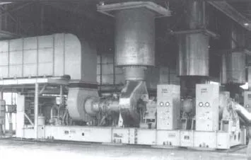
Figure 1-4. Turbine-driven centrifugal compressor package. The turbine draws air in from the large duct on the left. This is mixed with fuel and ignited. The jet of gas thus created causes the turbine blades to turn at high speed before being exhausted vertically upward through the large cylindrical duct. The turbine shaft drives the two centrifugal compressors, which are located behind the control cabinets on the tight end of the skid.
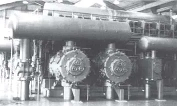
Figure 1-5. A 5500-Bhp integral reciprocating compressor. The sixteen power cylinders located at the top of the unit (eight on each side) drive a crankshaft that is directly coupled to the horizontal compressor cylinders facing the camera. Large cylindrical “bottles” mounted above and below the compressor cylinders filter out acoustical pulsations in the gas being compressed.
Usually, the separated gas is saturated with water vapor and must be dehydrated to an acceptable level, normally less than 7 lb/MMscf (110 mg H2O/Sm3). This is normally done in a glycol dehydrator, such as that shown in Figure 1-6.
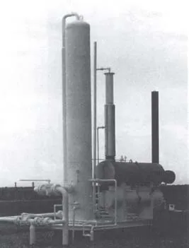
Figure 1-6. A small glycol gas dehydration system. The large vertical vessel on the left is the contact tower where “dry” glycol contacts the gas and absorbs water vapor. The upper horizontal vessel is the “reboiler” or “reconcentrator” where the wet glycol is heated, boiling off the water that exits the vertical pipe coming off the top just behind the contact tower. The lower horizontal vessel serves as a surge tank.
Dry glycol is pumped to the large vertical contact tower, where it strips the gas of its water vapor. The wet glycol then flows through a separator to the large horizontal reboiler, where it is heated and the water boiled off as steam.
In some locations it may be necessary to remove the heavier hydrocarbons to lower the hydrocarbon dew point. Contaminants such as H2S and CO2 may be present at levels higher than those acceptable to the gas purchaser. If this is the case, then additional equipment will be necessary to “sweeten” the gas.
The oil and emulsion from the separators must be treated to remove water. Most oil contracts specify a maximum perce...