
eBook - ePub
FLAC and Numerical Modeling in Geomechanics
Christine Detournay, Roger Hart, Christine Detournay, Roger Hart
This is a test
- 528 pages
- English
- ePUB (adapté aux mobiles)
- Disponible sur iOS et Android
eBook - ePub
FLAC and Numerical Modeling in Geomechanics
Christine Detournay, Roger Hart, Christine Detournay, Roger Hart
Détails du livre
Aperçu du livre
Table des matières
Citations
À propos de ce livre
Sixty-five papers cover a wide range of topics from engineering applications to theoretical developments in the areas of embankment and slope stability, underground cavity design and mining; dynamic analysis, soil and structure interaction, and coupled processes and fluid flow.
Foire aux questions
Comment puis-je résilier mon abonnement ?
Il vous suffit de vous rendre dans la section compte dans paramètres et de cliquer sur « Résilier l’abonnement ». C’est aussi simple que cela ! Une fois que vous aurez résilié votre abonnement, il restera actif pour le reste de la période pour laquelle vous avez payé. Découvrez-en plus ici.
Puis-je / comment puis-je télécharger des livres ?
Pour le moment, tous nos livres en format ePub adaptés aux mobiles peuvent être téléchargés via l’application. La plupart de nos PDF sont également disponibles en téléchargement et les autres seront téléchargeables très prochainement. Découvrez-en plus ici.
Quelle est la différence entre les formules tarifaires ?
Les deux abonnements vous donnent un accès complet à la bibliothèque et à toutes les fonctionnalités de Perlego. Les seules différences sont les tarifs ainsi que la période d’abonnement : avec l’abonnement annuel, vous économiserez environ 30 % par rapport à 12 mois d’abonnement mensuel.
Qu’est-ce que Perlego ?
Nous sommes un service d’abonnement à des ouvrages universitaires en ligne, où vous pouvez accéder à toute une bibliothèque pour un prix inférieur à celui d’un seul livre par mois. Avec plus d’un million de livres sur plus de 1 000 sujets, nous avons ce qu’il vous faut ! Découvrez-en plus ici.
Prenez-vous en charge la synthèse vocale ?
Recherchez le symbole Écouter sur votre prochain livre pour voir si vous pouvez l’écouter. L’outil Écouter lit le texte à haute voix pour vous, en surlignant le passage qui est en cours de lecture. Vous pouvez le mettre sur pause, l’accélérer ou le ralentir. Découvrez-en plus ici.
Est-ce que FLAC and Numerical Modeling in Geomechanics est un PDF/ePUB en ligne ?
Oui, vous pouvez accéder à FLAC and Numerical Modeling in Geomechanics par Christine Detournay, Roger Hart, Christine Detournay, Roger Hart en format PDF et/ou ePUB ainsi qu’à d’autres livres populaires dans Ciencias físicas et Geología y ciencias de la Tierra. Nous disposons de plus d’un million d’ouvrages à découvrir dans notre catalogue.
Informations
Embankment and slope stability
ABSTRACT: The factor of safety of a slope can be computed with FLAC by reducing the soil shear strength in stages until the slope fails. The resulting factor of safety is the ratio of the soil’s actual shear strength to the reduced shear strength at failure. This “shear strength reduction technique” has a number of advantages over slope stability analysis with the method of slices. Most importantly, the critical failure surface is found automatically and failure mechanisms involving deforming wedges of soil can be analyzed. The strength reduction technique is illustrated through a number of examples including a simple embankment, rotational failure of a cantilever sheet pile wall, 3D slope stability of a circular hole, and stability of a gravity retaining wall.
1 INTRODUCTION
The finite element method was used for slope stability analysis as early as 1966 (Brown & King, 1966), but applications have been limited because of the long computer ran times required. Now, with faster computers, finite element slope stability analysis is becoming a practical alternative to the method of slices and is being used increasingly in engineering practice.
One approach to computing a factor of safety with a finite element code is to reduce the soil shear strength in stages to bring a slope into a state of limiting equilibrium. A slope problem is solved for progressively lower shear strength until failure occurs. The factor of safety is defined as the ratio of the soil’s actual shear strength to the reduced shear strength at failure. This “shear strength reduction technique” has a number of advantages over method-of-slices analysis. First, the critical failure surface is found automatically and it is not necessary to specify the shape of the failure surface (circular, log spiral, piecewise linear, etc) in advance. Second, failure mechanisms involving deforming wedges of soil can be analyzed. Deforming wedges are important for rotational failure of retaining walls and sheet pile walls, and for 3D slope stability problems. This type of failure mechanism cannot be handled with the method of slices, which assumes failure only along discrete slip surfaces.
In this paper, the shear strength reduction technique is illustrated through a number of examples. The basic technique is demonstrated for a simple homogenous embankment. Then, two problems involving deforming wedges are analyzed: rotational failure of a cantilever sheet pile wall and 3D slope stability of a vertical circular hole. Finally, the stability of a gravity retaining wall is studied, comparing strength reduction factors of safety to traditional sliding and rotational factors of safety.
2 THE STRENGTH REDUCTION TECHNIQUE
For slopes and embankments, the factor of safety F is traditionally defined as the ratio of the actual soil shear strength to the minimum shear strength required to prevent failure (Bishop, 1955). The factor of safety is defined by comparing two materials, one actual and one fictitious, one with the actual soil strength and one with the strength reduced to the point at which the slope fails. As Duncan (1996) points out, F is the factor by which the soil shear strength must be divided to bring the slope to the verge of failure.
Since the factor of safety is defined as a shear strength reduction factor, an obvious way of computing it with a finite element code is to reduce the soil shear strength until collapse occurs. The resulting factor of safety is the ratio of the soil’s actual shear strength to the reduced shear strength at failure. This approach was used as early as 1975 by Zienkiewicz, Humpheson & Lewis (1975), and has since been applied by Naylor (1982), Donald & Giam (1988), Matsui & San (1992), Ugai (1989), Ugai & Leshchinsky (1995) and others.
To perform slope stability analysis with the shear strength reduction technique, simulations are ran for a series of trial factors of safety Ftrial with the soil cohesion c and angle of internal friction ϕ reduced according to the equations:
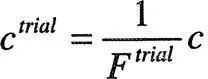 | (1) |
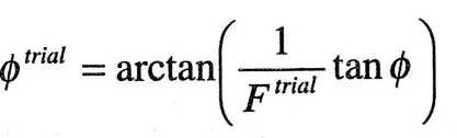 | (2) |
Previous studies have found the limit state, by reducing the shear strength in small steps until collapse occurs. We have found that bracketing and bisection is faster. First, upper and lower brackets are established. The initial lower bracket is any trial factor of safety at which a simulation converges to equilibrium. The initial upper bracket is any trial factor of safety for which the simulation does not converge. Next, a point midway between the upper and lower brackets is tested. If the simulation converges, the lower bracket is replaced by this new value. If the simulation does not converge, the upper bracket is replaced. The process is repeated until the difference between upper and lower brackets is less than a specified tolerance.
3 CONVERGENCE CRITERION
For FLAC, the convergence criterion, to determine if a simulation has reached equilibrium, is the maximum nodal unbalanced force. The unbalanced force is the sum of forces acting on a node from its neighboring elements. If a node is in equilibrium, these forces should sum to zero. Thus, the unbalanced force is a measure of how far from equilibrium a particular node is.
To determine if a simulation has reached equilibrium, the numerical mesh is searched for the node with the greatest unbalanced force. This maximum unbalanced force is then normalized by the gravitational body force acting on that node. In a numerical simulation the unbalanced force will never be exactly equal to zero and an acceptable lower limit must be chosen. For...