Physics
Aberrations
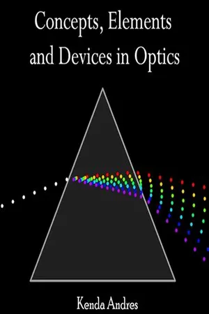
Aberrations in physics refer to deviations or distortions in the behavior of waves or particles, leading to errors or imperfections in the formation of an image or the transmission of light. These deviations can occur in optical systems, such as lenses or mirrors, and can result in blurring, distortion, or color fringing. Aberrations are important to understand in order to optimize the performance of optical instruments.
Written by Perlego with AI-assistance
Related key terms
1 of 5
10 Key excerpts on "Aberrations"
 No longer available |Learn more
- (Author)
- 2014(Publication Date)
- Library Press(Publisher)
________________________ WORLD TECHNOLOGIES ________________________ Chapter- 1 Optical Aberration Aberrations are departures of the performance of an optical system from the predictions of paraxial optics. Aberration leads to blurring of the image produced by an image-forming optical system. It occurs when light from one point of an object after trans-mission through the system does not converge into (or does not diverge from) a single point. Instrument-makers need to correct optical systems to compensate for aberration. The articles on reflection, refraction and caustics discuss the general features of reflected and refracted rays. Overview Aberrations fall into two classes: monochromatic and chromatic . Monochromatic aber-rations are caused by the geometry of the lens and occur both when light is reflected and when it is refracted. They appear even when using monochromatic light, hence the name. Chromatic Aberrations are caused by dispersion, the variation of a lens's refractive index with wavelength. They do not appear when monochromatic light is used. Monochromatic aberration The elementary theory of optical systems leads to the theorem: Rays of light proceeding from any object point unite in an image point ; and therefore an object space is reproduced in an image space. The introduction of simple auxiliary terms, due to C. F. Gauss ( Dioptrische Untersuchungen , Göttingen, 1841), named the focal lengths and focal planes, permits the determination of the image of any object for any system. The Gaussian theory, however, is only true so long as the angles made by all rays with the optical axis (the symmetrical axis of the system) are infinitely small, i.e. with infinitesimal objects, images and lenses; in practice these conditions are not realized, and the images projected by uncorrected systems are, in general, ill defined and often completely blurred, if the aperture or field of view exceeds certain limits. No longer available |Learn more
- (Author)
- 2014(Publication Date)
- Academic Studio(Publisher)
________________________ WORLD TECHNOLOGIES ________________________ Chapter 8 Optical Aberration Aberrations are departures of the performance of an optical system from the predictions of paraxial optics. Aberration leads to blurring of the image produced by an image-forming optical system. It occurs when light from one point of an object after trans-mission through the system does not converge into (or does not diverge from) a single point. Instrument-makers need to correct optical systems to compensate for aberration. Overview Aberrations fall into two classes: monochromatic and chromatic . Monochromatic aberr-ations are caused by the geometry of the lens and occur both when light is reflected and when it is refracted. They appear even when using monochromatic light, hence the name. Chromatic Aberrations are caused by dispersion, the variation of a lens's refractive index with wavelength. They do not appear when monochromatic light is used. Monochromatic Aberrations • Piston • Tilt • Defocus • Spherical aberration • Coma • Astigmatism • Field curvature • Image distortion Piston and tilt are not actually true optical Aberrations, as they do not represent or model curvature in the wavefront. If an otherwise perfect wavefront is aberrated by piston and tilt, it will still form a perfect, aberration-free image, only shifted to a different position. Defocus is the lowest-order true optical aberration. Chromatic Aberrations • Axial, or longitudinal, chromatic aberration ________________________ WORLD TECHNOLOGIES ________________________ • Lateral, or transverse, chromatic aberration Monochromatic aberration The elementary theory of optical systems leads to the theorem: Rays of light proceeding from any object point unite in an image point ; and therefore an object space is reproduced in an image space. The introduction of simple auxiliary terms, due to C. No longer available |Learn more
- (Author)
- 2014(Publication Date)
- Academic Studio(Publisher)
____________________ WORLD TECHNOLOGIES ____________________ Chapter 4 Optical Aberration Aberrations are departures of the performance of an optical system from the predictions of paraxial optics. Aberration leads to blurring of the image produced by an image-forming optical system. It occurs when light from one point of an object after transmission through the system does not converge into (or does not diverge from) a single point. Instrument-makers need to correct optical systems to compensate for aberration. The articles on reflection, refraction and caustics discuss the general features of reflected and refracted rays. Overview Aberrations fall into two classes: monochromatic and chromatic . Monochromatic Aberrations are caused by the geometry of the lens and occur both when light is reflected and when it is refracted. They appear even when using monochromatic light, hence the name. Chromatic Aberrations are caused by dispersion, the variation of a lens's refractive index with wavelength. They do not appear when monochromatic light is used. Monochromatic Aberrations • Piston • Tilt • Defocus • Spherical aberration • Coma • Astigmatism • Field curvature • Image distortion Piston and tilt are not actually true optical Aberrations, as they do not represent or model curvature in the wavefront. If an otherwise perfect wavefront is aberrated by piston and ____________________ WORLD TECHNOLOGIES ____________________ tilt, it will still form a perfect, aberration-free image, only shifted to a different position. Defocus is the lowest-order true optical aberration. Chromatic Aberrations • Axial, or longitudinal, chromatic aberration • Lateral, or transverse, chromatic aberration Monochromatic aberration The elementary theory of optical systems leads to the theorem: Rays of light proceeding from any object point unite in an image point ; and therefore an object space is reproduced in an image space. The introduction of simple auxiliary terms, due to C. No longer available |Learn more
- (Author)
- 2014(Publication Date)
- Research World(Publisher)
____________________ WORLD TECHNOLOGIES ____________________ Chapter 4 Optical Aberration Aberrations are departures of the performance of an optical system from the predictions of paraxial optics. Aberration leads to blurring of the image produced by an image-forming optical system. It occurs when light from one point of an object after transmission through the system does not converge into (or does not diverge from) a single point. Instrument-makers need to correct optical systems to compensate for aberration. The articles on reflection, refraction and caustics discuss the general features of reflected and refracted rays. Overview Aberrations fall into two classes: monochromatic and chromatic . Monochromatic Aberrations are caused by the geometry of the lens and occur both when light is reflected and when it is refracted. They appear even when using monochromatic light, hence the name. Chromatic Aberrations are caused by dispersion, the variation of a lens's refractive index with wavelength. They do not appear when monochromatic light is used. Monochromatic Aberrations • Piston • Tilt • Defocus • Spherical aberration • Coma • Astigmatism • Field curvature • Image distortion ____________________ WORLD TECHNOLOGIES ____________________ Piston and tilt are not actually true optical Aberrations, as they do not represent or model curvature in the wavefront. If an otherwise perfect wavefront is aberrated by piston and tilt, it will still form a perfect, aberration-free image, only shifted to a different position. Defocus is the lowest-order true optical aberration. Chromatic Aberrations • Axial, or longitudinal, chromatic aberration • Lateral, or transverse, chromatic aberration Monochromatic aberration The elementary theory of optical systems leads to the theorem: Rays of light proceeding from any object point unite in an image point ; and therefore an object space is reproduced in an image space. The introduction of simple auxiliary terms, due to C.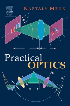 eBook - PDF
- Naftaly Menn(Author)
- 2004(Publication Date)
- Academic Press(Publisher)
Chapter 2 Theory of Imaging 2.1. Optical Aberrations 2.1.1. General Consideration. Ray Fan and Aberration Plot. Concept of Wave Aberrations We will proceed by considering the concept of imaging as described in Section 1.2 of Chapter 1 and pay most attention to the real imaging situation experienced in practice. Figure 2.1 demonstrates the basic difference between ideal imaging and real imaging. Let the rays originating in a point source A come to the system, each one at a different angle u . If the medium is homogeneous (has the same refrac-tive index everywhere) the wavefront W in the object space is a sphere. If in the image space all rays intersect at a single point A then the beam remains homo-centric, with a spherical wavefront W , and A is a stigmatic (ideal) image of A. However, in most situations this does not happen and the rays of different angles u come to different points on the axis OO (or, for tilted beams, to different off-axis locations). As a result, the real wavefront in the image space is not spherical, the homocentricity of the output beam is violated, and instead of a sharp point image there is a blurred spot. Such violation of stigmatic imaging is defined as optical Aberrations. Numerically Aberrations are characterized by the deviation of a real image A from the ideal image A 0 obtained in the paraxial range. This deviation can be determined either by the horizontal segment, δ s , along the optical axis, as in Fig. 2.2 (and then it is called the lateral aberration) or it can be related to the vertical segment ρ (then it is called the transverse aberration). The geometrical 41 42 2 ♦ Theory of Imaging Figure 2.1 (a) Ideal imaging and (b) real imaging. Figure 2.2 (a) Lateral and transverse aberration and (b) the aberration diagram. relation between lateral and transverse Aberrations is quite obvious: ρ = δ s × tan u ≈ δ s h S (2.1) in which the fact is taken into account that δ s S . eBook - PDF
Lens Design
A Practical Guide
- Haiyin Sun(Author)
- 2016(Publication Date)
- CRC Press(Publisher)
55 2 Optical Aberrations Any real optical system contains various Aberrations. The main task of optical design is to minimize these Aberrations. In this chapter, we briefly describe the five important Aberrations: spherical aberration, coma, astigmatism, field curvature, and image distortion. These five Aberrations are monochromatic. We will also describe two chromatic Aberrations: longitudinal color and lateral color. 2.1 SPHERICAL ABERRATION 2.1.1 REFLECTION SPHERICAL ABERRATION The most commonly seen aberration is the spherical aberration. Figure 2.1a shows a spherical mirror focusing a ray parallel to its optical axis. The mirror surface has a radius of curvature R, the incident ray has a height of h to the optical axis, and the focused spot is a distance of x away from the center of surface curvature. The incident ray hits one point on the mirror surface and has an angle of θ to the normal of this point on the surface. The reflected ray also has an angle of θ to the normal according to the reflection law. From Figure 2.1a, we have sin( ) θ = h R (2.1) cos( ) θ = R x /2 (2.2) Equation 2.2 holds because the distance between the focused spot and the point where the ray hits the mirror surface also equals to x. Combining Equations 2.1 and 2.2 to solve for the spherical aberration SA = x − R/2, we obtain SA x R R h R = - = - - 2 2 1 1 1 2 0 5 . (2.3) From Equation 2.3, we can see that for a given mirror, the spherical aberration varies as the height of the incident ray varies. When h → 0, SA → 0 and x → R/2. So, R/2 is the paraxial focal length of the mirror. We usually omit the term “par- axial” and simply use the term “focal length.” For h > 0, SA > 0. 56 Lens Design Plotted in Figure 2.1b is a raytracing diagram generated by Zemax showing the spherical aberration of a spherical mirror. Spherical aberration prevents a group of parallel rays being focused at the same spot and is an undesired property. No longer available |Learn more
- (Author)
- 2014(Publication Date)
- Orange Apple(Publisher)
________________________ WORLD TECHNOLOGIES ________________________ Chapter- 8 Optical Aberration Aberrations are departures of the performance of an optical system from the predictions of paraxial optics. Aberration leads to blurring of the image produced by an image-forming optical system. It occurs when light from one point of an object after transmission through the system does not converge into (or does not diverge from) a single point. Instrument-makers need to correct optical systems to compensate for aberration. Overview Aberrations fall into two classes: monochromatic and chromatic . Monochromatic Aberrations are caused by the geometry of the lens and occur both when light is reflected and when it is refracted. They appear even when using monochromatic light, hence the name. Chromatic Aberrations are caused by dispersion, the variation of a lens's refractive index with wavelength. They do not appear when monochromatic light is used. Monochromatic Aberrations • Piston • Tilt • Defocus • Spherical aberration • Coma • Astigmatism • Field curvature • Image distortion ________________________ WORLD TECHNOLOGIES ________________________ Piston and tilt are not actually true optical Aberrations, as they do not represent or model curvature in the wavefront. If an otherwise perfect wavefront is aberrated by piston and tilt, it will still form a perfect, aberration-free image, only shifted to a different position. Defocus is the lowest-order true optical aberration. Chromatic Aberrations • Axial, or longitudinal, chromatic aberration • Lateral, or transverse, chromatic aberration Monochromatic aberration The elementary theory of optical systems leads to the theorem: Rays of light proceeding from any object point unite in an image point ; and therefore an object space is reproduced in an image space. The introduction of simple auxiliary terms, due to C. eBook - PDF
- Hermann Wollnik(Author)
- 2012(Publication Date)
- Academic Press(Publisher)
8 Image Aberrations Trajectories of charged particles relative to an optic axis have been described throughout this book in terms of a Gaussian or first-order approxi-mation. This description is adequate for narrow particle beams; however, for realistic beams, deviations from this first-order theory are often observed: the Aberrations of second, third, and higher order. Normally, these aberra-tions are only of interest in image-profile planes where the particle beam is concentrated to a small cross section. For such image-profile planes, however, a correction of Aberrations is highly desirable. To determine the magnitudes of Aberrations of an optical system is rather involved. For the design of high-performance optical systems, on the other hand, it is sufficient to know the origin of Aberrations and to understand their interdependence. For this reason, the detailed derivation of image Aberrations is outlined only in the Appendix to this chapter. 8.1 S Y S T E M A T I C S OF IMAGE Aberrations The geometry of an optical system is defined by the geometry of its optic axis. This optic axis is straight in field-free regions or quadrupoles (see Fig. 210 8.1 S y s t e m a t i c s of I m a g e Aberrations 211 3.1) and circular, with p 0 the radius of curvature, in radially inhomogeneous sector fields (see Figs. 4.1, 4.16, and 4.17). The electrostatic potential in all these fields is constant along the optic axis (Chapters 3 and 4), as is the magnitude of the electric or magnetic field E 0 or B 0 . Thus, a particle can move along the optic axis if it has a rest mass m 0 0 , energy K 0 , and charge (z 0 e) 9 or, in other words, rigidities χ 0 = E 0 p E0 or χ 0 = B O P BO-To describe the trajectory of an arbitrary particle, we must define its energy-charge as well as its mass-charge ratios: K. Kr . . Win Winn (ze) (z 0 e) (ze) (z 0 e) [Eqs. (2.15), (2.16b) and (2.16c)]. eBook - PDF
Building Electro-Optical Systems
Making It All Work
- Philip C. D. Hobbs(Author)
- 2021(Publication Date)
- Wiley(Publisher)
Thus the heroic lens design is someone else’s problem – the rest of us mostly live in the low-NA, narrow field region behind those fancy lenses. Instrument designers need to know how Aberrations propagate, what produces them, and how to avoid doing it. For this use, the lowest-order Aberrations are generally enough. For the same reason, we’ll ignore the pure ray picture entirely, and center on phase shifts of the plane wave components of a focused spot at an arbitrary field position. 9.4.1 Aberration Nomenclature Aberration theory is somewhat separate from the rest of optics, because it is primarily used by lens designers, who have been doing much the same sort of work for 100 years, in sharp distinction to workers in most of the rest of optics. This is not to disparage the great strides lens design has made in that time, but it remains true that the formalism of classical aberration theory is not clearly related to the rest of the optical world, and a number of the terms used have different meanings than they have elsewhere. For example, to most practical optics folk, defocus means that the focal plane is offset from where it should be. In the paraxial approximation, a defocus d translates to a quadratic phase (time delay) across the pupil, Δ t defocus ≈ nd c ( 1 − u 2 2 ) , (9.51) whereas the real phase delay is k z z , which in time delay terms is Δ t defocus = nd c cos 𝜃 = nd c √ 1 − u 2 , (9.52) which of course contains all even orders in u . In wave aberration theory, defocus means the quadratic expression (9.51), even at large NA . A pure focus shift in a large-NA system thus comes out as Aberrations of all even orders, including spherical aberration and so on, even though a twist of the focus knob will restore the image completely. Those of us who use physical intuition heavily must guard against being led astray by this sort of thing. eBook - PDF
- José Alonso, José A. Gómez-Pedrero, Juan A. Quiroga(Authors)
- 2019(Publication Date)
- Cambridge University Press(Publisher)
6 Aberrations and Lens Design 6.1 Introduction In previous chapters, we studied and analyzed the optical properties of ophthalmic lenses under the paraxial approximation of geometrical optics. This theory constitutes a useful and powerful way to analytically describe the image-forming properties of ophthalmic lenses, and it allows the computation of important magnitudes such as lens power, ray or eye deviation (prismatic effect), or magnification. Within the framework of paraxial optics, any system behaves as an ideal imaging system, fulfilling the so-called Maxwell’s conditions for a perfect imaging system. However, paraxial approximation is not accurate enough to completely describe the behavior of most real systems, including ophthalmic lenses. In general, an optical system will present some degree of image degradation due to the effect of Aberrations. Aberrations appear because the trajectories actually followed by rays, determined by applying Snell’s law at the points where rays intersect with the surfaces of the optical system, differ from those predicted within the paraxial approximation. Indeed, a fundamental part of geometric optics is the so-called nonparaxial optics, also known as the theory of Aberrations, which studies the imaging properties of optical systems outside the scope of the paraxial approximation. It is important to understand the difference between paraxial and nonparaxial optics. As part of geometric optics, both theories share a common methodology: the study of optical systems through the analysis of the trajectories followed by the light rays propagating within them. In paraxial optics, a first-order approximation to the Snell law is used and the surface sags are neglected when computing the intersection of rays with surfaces. In nonparaxial optics, the degree of approximation is reduced and, consequently, the light trajectories are more realistic.
Index pages curate the most relevant extracts from our library of academic textbooks. They’ve been created using an in-house natural language model (NLM), each adding context and meaning to key research topics.