![]()
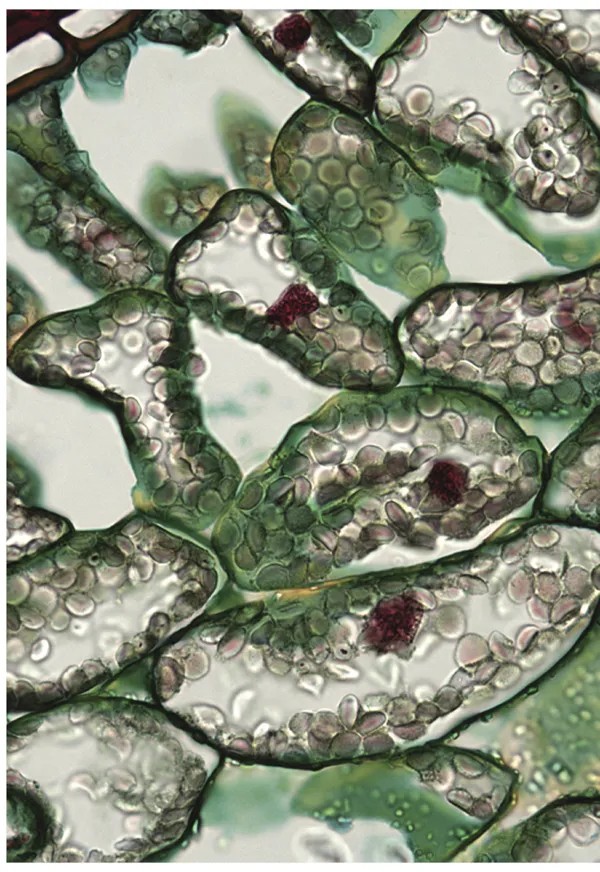
Brightfield microscopy of stained mesophyll cells in a leaf section.
CHAPTER 1
FUNDAMENTALS OF LIGHT MICROSCOPY
OVERVIEW
In this chapter, we examine the optical design of the light microscope and review procedures for adjusting the microscope and its illumination to obtain the best optical performance. The light microscope contains two distinct sets of interlaced focal planes, eight planes in all, between the illuminator and the eye. All of these planes play an important role in image formation. As we will see, some planes are not fixed, but vary in their location depending on the focus position of the objective and condenser lenses. Therefore, an important first step is to adjust the microscope and its illuminator for Koehler illumination, a method of illumination introduced by August Koehler in 1893 that gives bright, uniform illumination of the specimen and simultaneously positions the sets of image and diffraction planes at their proper locations. We will refer to these locations frequently throughout the book. Indeed, microscope manufacturers build microscopes so that filters, prisms, and diaphragms are located at precise physical locations in the microscope body, assuming that certain focal planes will be precisely located after the user has adjusted the microscope for Koehler illumination. Finally, we will practice adjusting the microscope for examining a stained histological specimen, review the procedure for determining magnification, and measure the diameters of cells and nuclei in a tissue sample.
OPTICAL COMPONENTS OF THE LIGHT MICROSCOPE
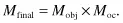
A compound light microscope is an optical instrument that uses visible light to produce a magnified image of an object (or specimen) that is projected onto the retina of the eye or onto the photosensitive surface of an imaging device. The word compound refers to the fact that two lenses, the objective and the eyepiece (or ocular), work together to produce the final magnification M of the image such that:
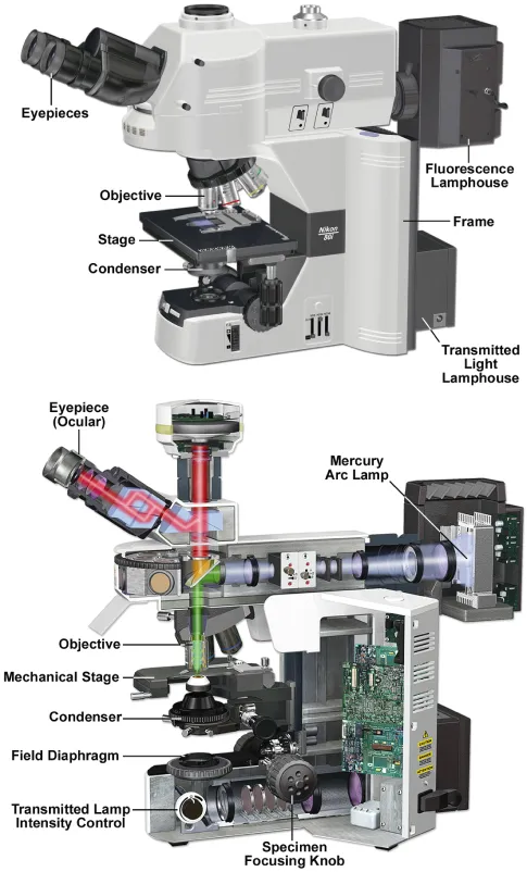
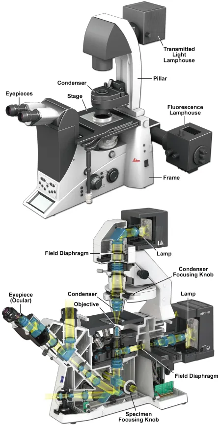
Two microscope components are of critical importance in forming the image: (1) the objective, which collects light diffracted by the specimen and forms a magnified real image at what is called the real intermediate image plane near the eyepieces or oculars, and (2) the condenser, which focuses light from the illuminator onto a small area of the specimen. (We define real vs. virtual images and examine the geometrical optics of lenses and magnification in Chapter 4; a real image can be viewed on a screen or exposed on a sheet of film, whereas a virtual image cannot.) The arrangement of these and other components in an upright stand research level microscope is shown in Figure 1.1, and for an inverted research microscope in Figure 1.2. Two lamps provide illumination for brightfield and interference (illumination from below: diascopic) and fluorescence (illumination from above: episcopic) modes of examination. Both the objective and condenser contain multiple lens elements that perform close to their theoretical limits and are therefore expensive. As these optics are handled frequently, they require careful attention. Other components less critical to image formation are no less deserving of care, including the tube lens and eyepieces, the lamp collector and lamp socket and its cord, filters, polarizers, retarders, and the microscope stage and stand with coarse and fine focus.
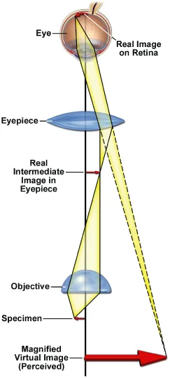
At this point, take time to examine Figure 1.3, which shows how an image becomes magnified and is perceived by the eye. The figure also points out the locations of important focal planes in relation to the objective, the ocular, and the eye. The specimen on the microscope stage is examined by the objective, which produces a magnified real image of the object in the image plane of the ocular. When looking in the microscope, the ocular acting together with the eye’s cornea and lens projects a still more magnified real image onto the retina, where it is perceived and interpreted by the brain as a magnified virtual image about 25 cm (10 in) in front of the eye. For photography, the intermediate image is recorded directly or projected as a real image onto a camera.
Microscopes come in both inverted and upright designs (Figs. 1.1 and 1.2). In both designs the location of the real intermediate image plane at the eyepiece is fixed, and the focus dial of the microscope is used to position the image at precisely this location. In most conventional upright microscopes, the objectives are attached to a nosepiece turret on the microscope body, and the focus control moves the specimen stage up and down to bring the image to its proper location in the eyepiece. In inverted designs, the stage itself is fixed, being bolted to the microscope body, and the focus dials move the objective turret up and down to position the image in the eyepieces. Inverted microscopes are rapidly gaining in popularity because one can examine living cells in culture dishes filled with medium using standard objectives and avoid the use of sealed flow chambers, which can be awkward. One also has better access to the stage, which can serve as a rigid working platform for microinjection and physiological recording equipment. Inverted designs also have their center of mass closer to the lab bench and are therefore less sensitive to vibration. However, there is some risk of physical damage, as objectives may rub against the bottom surface of the stage during rotation of the objective turret. Oil immersion objectives are also at risk, because gravity can cause oil to drain down and enter the crevice between the nose and barrel, potentially contaminating internal lens surfaces, ruining the optical performance and resulting in costly lens repair. This can be prevented by wrapping a pipe cleaner or hair band around the upper part of the lens to catch excess drips of oil. Therefore, despite many advantages, inverted research microscopes require a little more attention than do standard upright designs.
APERTURE AND IMAGE PLANES IN A FOCUSED, ADJUSTED MICROSCOPE
Principles of geometrical optics show that a microscope has two sets of interlaced conjugate focal planes, a set of four object or field planes, and a set of 4 aperture or diffraction planes, that have fixed, defined locations with respect to the object, optical elements, the light source, and the eye or camera. Each plane within a set is conjugate with the other planes, with the consequence that all of the planes of a given set can be seen simultaneously when looking in the microscope. The field planes are observed in normal viewing mode using the eyepieces. This mode of viewing is called the normal, or object, or orthoscopic mode, and the real image of an object is called an orthoscopic image. Viewing the aperture or diffraction planes requires using an eyepiece telescope or Bertrand lens, which is focused on the rear aperture of the objective (see Note). This mode of viewing is called the aperture, or diffraction, or conoscopic mode, and the image of the diffraction plane viewed at this location is called the conoscopic image. In this text, we refer to the two viewing modes as the normal and aperture viewing modes and do not use the terms orthoscopic and conoscopic, although these terms are common in other texts.
Note: Objectives, Eyepieces, and Eyepiece Telescopes
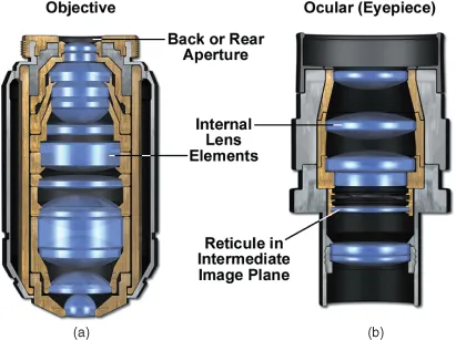
An aperture is a hole or opening in an opaque mask designed to eliminate stray light from entering the light path, and most field and aperture planes of a microscope contain them. A fixed circular aperture is found at or near the rear focal plane of the objective (Fig. 1.4). (The precise location of the rear focal plane is a function of the focal length of the lens; for objectives with short focal lengths, the focal plane may be located inside the lens barrel.) The aperture mask is plainly visible at the back surface of the objective. This aperture marks one of the key aperture planes of the microscope, and we refer to this site frequently in the text.
The eyepiece telescope (not shown), sometimes called a phase or centering telescope, is a special focusable eyepiece that is used in place of an ocular to view the rear aperture of the objective and other aperture planes that are conjugate to it. To use the telescope, remove an eyepiece, insert the eyepiece telescope, and focus it on the circular edge of the objective rear aperture. Some microscopes contain a built-in focusable telescope lens called a Bertrand lens that can be conveniently rotated into and out of the light path as required.
The identities of the sets of conjugate focal planes are listed in Table 1.1, and their locations in the microscope under conditions of Koehler illumination are shown in Figure 1.5. The terms front aperture and rear aperture refer to the openings at the front and rear focal planes of a lens from the perspective of a light ray traveling from the lamp to the retina. Knowledge of the location of these planes is essential for adjusting the microscope and for understanding the principles involved in image formation. Indeed, the entire design of a microscope is based around these planes and the user’s need to have access...