Physics
Demultiplexer
A demultiplexer, or demux, is a device that takes a single input and directs it to one of several output lines. In physics, demultiplexers are used to separate a single input signal into multiple channels, allowing for the transmission of data to different destinations. This process is essential for various applications, including telecommunications and data processing.
Written by Perlego with AI-assistance
Related key terms
1 of 5
8 Key excerpts on "Demultiplexer"
- eBook - ePub
PIC16F1847 Microcontroller-Based Programmable Logic Controller
Intermediate Concepts
- Murat Uzam(Author)
- 2020(Publication Date)
- CRC Press(Publisher)
5 Demultiplexer MacrosIntroduction
A Demultiplexer, abbreviated DMUX, is used when a circuit is to send a signal to one of many devices. This description sounds similar to the description given for a decoder, but a decoder is used to select among many devices, whereas a Demultiplexer is used to send a signal among many devices. However, any decoder having an enable line can function as a Demultiplexer. If the enable line of a decoder is used as a data input, then the data can be routed to any one of the outputs, and, thus, in that case, the decoder can be used as a Demultiplexer. As the name implies, a Demultiplexer performs the opposite function to that of a multiplexer. A single input signal can be connected to any one of the output lines provided by the choice of an appropriate select signal. The general form of a 1-to-n Demultiplexer can be seen in Figure 5.1 . If there are “m ” select inputs , then the number of output lines to which the data can be routed is n = 2m. Although, not shown in Figure 5.1 , in addition to the other inputs, the Demultiplexer may have an enable line, E , for enabling it. When the Demultiplexer is disabled with E set to 0 (for active-high enable input E - eBook - PDF
- Somayeh Mohammady(Author)
- 2019(Publication Date)
- IntechOpen(Publisher)
7 Section 2 Multiplexing Basics 9 Chapter 2 Multiplexing Vijayakumar Nandalal and M.S. Sumalatha Abstract In any communication system that is either digital or analog, we need a com-munication channel for transmission. This channel can be a wired or a wireless link. It is not practical to allocate individual channels for each user. Therefore a group of signals are combined together and sent over a common channel. For this we use multiplexers. A multiplexer is a device that allows digital information from several sources to be routed onto a single line for transmission to a single destination. A Demultiplexer does the reverse operation of multiplexing. It takes digital informa-tion from a single line and distributes it to a given number of output lines. Keywords: frequency division multiplexing, time division multiplexing, code division multiplexing, wave length division multiplexing, orthogonal frequency division multiplexing, amplitude shift keying, frequency shift keying, phase shift keying 1. Introduction Multiplexing is the process of transmission of information from more than one source into a single signal over a shared medium. We can be able to multiplex analog or digital signal. If analog signals are multiplexed, then this type of multiplexer is called analog multiplexer. If digital signals are multiplexed, then this type of multiplexer is called digital multiplexer. The advantage of multiplexing is that we can transmit a large number of signals to a single medium. This channel can be a physical medium like a coaxial, metallic conductor or a wireless link and will have to handle multiple signals at a time. Thus the cost of transmission can be reduced. Figure 1. Classification of multiplexing techniques. Multiplexing 10 Even though the transmission occurs on the same channel, they do not necessarily occur at the same instant. - No longer available |Learn more
Data Communications and Computer Networks
A Business User's Approach
- Curt White, , , (Authors)
- 2021(Publication Date)
- Cengage Learning EMEA(Publisher)
As you might expect, the dynamic assignment of frequencies can be less wasteful than the static assignment of frequencies, which is found in terminal-to-mainframe computer multiplexed systems and television systems. In general, the device that accepts input from one or more users is called the multiplexor . The device attached to the receiving end of the medium that splits off each signal to deliver it to the appropriate receiver is called the second mul-tiplexor, or demultiplexor . In all frequency division multiplexing systems, the multiplexor accepts input from the user(s), converts the data streams to analog sig-nals using either fixed or dynamically assigned frequencies, and transmits the com-bined analog signals over a medium that has a wide enough bandwidth to support the total range of all the assigned frequencies. The demultiplexor then accepts the combined analog signals, separates out one or more of the individual analog sig-nals, and delivers these to the appropriate user(s). Figure 5-1 shows a simplified diagram of frequency division multiplexing. In this example, a number of radio stations have multiplexed their radio signals onto a band of frequencies. On the receiving end, individual radios employ a demultiplexor (a tuner) to separate each radio signal from the others. Figure 5-1 Simplified example of frequency division multiplexing FM Radio Stations and Towers Listener with FM Radio 97.3 MHz 101.7 MHz 98.9 MHz To keep one signal from interfering with another signal, a set of unused frequencies called a guard band is usually inserted between the two signals to provide a form of insulation. These guard bands take up frequencies that might be used for other data channels, thus introducing a certain level of wastefulness. Frequency division multiplexing was created during a time when most if not all data and signals were analog. - eBook - PDF
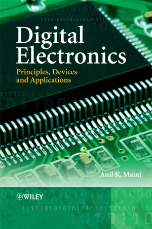
Digital Electronics
Principles, Devices and Applications
- Anil K. Maini(Author)
- 2007(Publication Date)
- Wiley(Publisher)
It routes the information present on the input line to any of the output lines. The output line that gets the information present on the input line is decided by the bit status of the selection lines. A decoder is a special case of a Demultiplexer without the input line. Figure 8.18(a) shows the circuit representation of a 1-to-4 Demultiplexer. Figure 8.18(b) shows the truth table of the Demultiplexer when the input line is held HIGH. A decoder, as mentioned earlier, is a combinational circuit that decodes the information on n input lines to a maximum of 2 n unique output lines. Figure 8.19 shows the circuit representation of 2-to-4, 3-to-8 and 4-to-16 line decoders. If there are some unused or ‘don’t care’ combinations in the n -bit code, then there will be fewer than 2 n output lines. As an illustration, if there are three input lines, it (b) I/P 1 1 1 1 A 0 0 1 1 B 0 1 0 1 D 0 1 0 0 0 D 1 0 1 0 0 D 2 0 0 1 0 D 3 0 0 0 1 1-to-4 DEMUX I/P line A B D 0 D 1 D 2 D 3 Select O/P (a) Figure 8.18 1-to-4 Demultiplexer. 286 Digital Electronics 0 1 2 3 2-to-4 A B 0 1 7 3-to-8 A B C 0 1 15 4-to-16 A B C D Figure 8.19 Circuit representation of 2-to-4, 3-to-8 and 4-to-16 line decoders. can have a maximum of eight unique output lines. If, in the three-bit input code, the only used three-bit combinations are 000, 001, 010, 100, 110 and 111 (011 and 101 being either unused or don’t care combinations), then this decoder will have only six output lines. In general, if n and m are respectively the numbers of input and output lines, then m ≤ 2 n . A decoder can generate a maximum of 2 n possible minterms with an n -bit binary code. In order to illustrate further the operation of a decoder, consider the logic circuit diagram in Fig. 8.20. This logic circuit, as we will see, implements a 3-to-8 line decoder function. This decoder has three inputs designated as A , B and C and eight outputs designated as D 0 , D 1 , D 2 , D 3 , D 4 , D 5 , D 6 and D 7 . - eBook - PDF
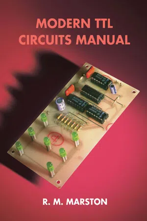
- R. M. Marston(Author)
- 2013(Publication Date)
- Newnes(Publisher)
separate lines. The above circuit is, of course, gready simplified, and in practice would need the addition of a pulse synchronization system and a few other refinements to make it work properly, but it does serve to illus-trate the basic multiplexing principle. Note in particular that multi-plexers and Demultiplexers are really meant to form individual ele-RECEIVER _ / S Special purpose ICs and circuits 195 merits in a highly specialized type of system, but that in practice a multiplexer actually functions as an addressable data selector (like SW1 in Figure 7.1), and a Demultiplexer functions as an addressable data distributor (like SW2 in Figure 7.1) or as a binary-code 'decoder', and in these modes both types of device are so useful that they are usually described as 'multiplexer/data-selector' and 'demul-tiplexer/decoder' ICs. Note in Figure 7.1 that SW1 and SW2 can both pass signals in either direction, and can thus be used as either multiplexers or Demultiplexers by simply placing them in the appropriate part of the system. TTL ICs, however, can only pass signals in one direction, and make such poor imitations of electro-mechanical switches that they have to be produced in both 'multiplexer' and 'Demultiplexer' versions. CMOS ICs, on the other hand, can be made to act as near-perfect bidirectional switches that can handle both digital and ana-logue signals; CMOS 'analogue switches' can thus be used as both multiplexers and Demultiplexers, but for many years were too slow for use in most TTL-type applications. Then, in the mid-1980s, the 74HC series of fast CMOS was introduced, and its superb range of analogue switch' ICs quickly made many of the existing TTL mul-tiplexer and Demultiplexer ICs obsolescent, the upshot being that rel-atively few of these devices are now available in TTL form. - eBook - ePub
- Fraidoon Mazda(Author)
- 2014(Publication Date)
- Butterworth-Heinemann(Publisher)
40Multiplexers
J Hoolan, Dowty Communications LtdPublisher Summary
The multiplexer is one of the most important components in communications networking. Its central function, from the network managers viewpoint, is to concentrate many users information on to a single transmission channel to maximize the efficiency of that channel. Given a transmission channel, there are two ways the available bandwidth can be used: first, by dividing the available bandwidth frequency spectrum into a subset of frequencies, each of which can then simultaneously use the transmission channel and allocate each frequency band to an input channel that needs to be multiplexed, or second, allocate all the available bandwidth to each channel for a fixed discrete time period. The first of these methods would be frequency division multiplexing and the latter time division multiplexing (TDM). As synchronous protocols evolved, the need to multiplex them grew; networks with remote sites that had a mix of asynchronous and synchronous terminals needed to connect them to the central site computing resource. Caught between the exponential growth of computing power and the use of asynchronous terminals as a cheap and convenient way of accessing computers, the statistical TDM was developed. It was first formulated in the early 1970s and in particular on the Arpanet network in the U.S.A from which the X.25 packet switch standard evolved.ContentsIntroduction Time Division Multiplexers Statistical time division multiplexing High order multiplexing Multiplexing and packet switching X.25 and OSI Physical layer standards Multiplexers in communications network The future of multiplexing40.1 Introduction
The multiplexer is one of the most important components in communications networking. Its central function, from the network managers viewpoint, is to concentrate many users (or information channels) on to a single transmission channel in order to maximise the efficiency of that channel: it is used in almost every aspect of networking digital data, voice and video. This section will describe the advantages and disadvantages of different data multiplexing techniques, why these different techniques evolved to solve particular network engineering problems and how they fit in to modern networks. - Norman F. Schneidewind(Author)
- 2012(Publication Date)
- Wiley-IEEE Press(Publisher)
1 .Table 1.30 Truth Table for 4-to-1 MultiplexerSelector Output S0 S1 Z 0 0 d0 0 1 d1 1 0 d2 1 1 d3 .DemultiplexersFigure 1.13 The 4-to-1 multiplexer block and logic diagrams.A Demultiplexer causes an input x to be transferred to one of 2n output lines, where n is the number of select inputs in Figure 1.14 . Output equations for a Demultiplexer with two select inputs and four outputs are shown in the truth table, Table 1.31 . The Demultiplexer does the reverse of the multiplexer; for example, it distributes Internet data, which have been multiplexed on input line x, to each of four microprocessor output ports d0 , d1 , d3 , and d4 .For example, Internet data will be distributed to output port d0 when in Table 1.31 .Table 1.31 Truth Table for 1-to-4 Demultiplexer.SEQUENTIAL CIRCUITSFigure 1.14 The 1-to-4 Demultiplexer block and logic diagrams.A clocked synchronous sequential circuit uses flip-flops to store data, and its outputs depend on both the previous and current values of inputs [HAR07]. These circuits are called state machines, wherein states are stored in flip-flops, and state changes are triggered by CPs. In an asynchronous sequential circuit- Steve Mackay, Edwin Wright, John Park(Authors)
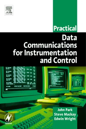
- 2003(Publication Date)
- Newnes(Publisher)
7 Modems and multiplexers This chapter reviews the concepts of modems and multiplexers, their practical use, position and importance in the operation of a data communications system. Objectives When you have completed studying this chapter you will be able to: • Explain the modes of operation of a modem • Describe the role of interchange circuits • Describe three methods of flow control • Explain the causes of signal distortion • Describe the different methods of modulation: – ASK – FSK – PSK – QAM – TCM • List and describe the components of a modem • Describe the properties of different modem types: – Dumb modems – Smart modems, including their states and commands • Describe radio modems: – Terms – Modes – Features – Spread spectrum modems • Describe the error detection protocols • Describe data compression techniques • List and describe the CCITT and Bell modem standards • Explain troubleshooting • Describe modem selection • Describe three multiplexing concepts 146 Practical Data Communications for Instrumentation and Control • Describe terminal multiplexers • Describe statistical multiplexers 7.1 Introduction Communications systems, whether they are telephone, landline, or radio, cannot directly transport digital information without some distortion of the signal. This is due to the bandwidth limitation inherent in any of the connecting mediums. A conversion device, called a modem (modulator/demodulator), is required to convert the digital signals generated by the transmitting computer, into an analogue form suitable for long distance transmission. The demodulator in the modem receives analogue information and converts it back to the original digital information. Figure 7.1 gives a schematic view of the place of the modem in the communications hierarchy. Figure 7.1 The modem as a component in a typical communication system The bandwidth in a telephone network, for example, is limited by cable capacitance and inductance.
Index pages curate the most relevant extracts from our library of academic textbooks. They’ve been created using an in-house natural language model (NLM), each adding context and meaning to key research topics.


