Physics
Reflection at Spherical Surfaces
Reflection at spherical surfaces refers to the phenomenon where light rays are reflected off a curved surface, such as a concave or convex mirror. The reflection follows the laws of reflection, with the incident angle being equal to the reflected angle. Spherical mirrors are used in various optical devices and systems, including telescopes, microscopes, and vehicle side mirrors.
Written by Perlego with AI-assistance
Related key terms
1 of 5
10 Key excerpts on "Reflection at Spherical Surfaces"
 eBook - PDF
- John D. Cutnell, Kenneth W. Johnson, David Young, Shane Stadler(Authors)
- 2021(Publication Date)
- Wiley(Publisher)
These angles are measured with respect to the normal, which is a line drawn perpendicular to the surface of the mirror at the point of incidence. (a) Specular reflection (b) Diffuse reflection FIGURE 25.4 (a) The drawing shows specular reflection from a polished plane surface, such as a mirror. The reflected rays are parallel to each other. (b) A rough surface reflects the light rays in all directions; this type of reflection is known as diffuse reflection. l Wave fronts Pulsating sphere Rays λ FIGURE 25.1 A hemispherical view of a sound wave emitted by a pulsating sphere. The wave fronts are drawn through the condensations of the wave, so the distance between two successive wave fronts is the wavelength λ. The rays are perpendicular to the wave fronts and point in the direction of the velocity of the wave. Rays Curved wave fronts Pulsating sphere (a) (b) Plane wave fronts FIGURE 25.2 (a) Portions of two spherical wave fronts are shown. The rays are perpendicular to the wave fronts and diverge. (b) For a plane wave, the wave fronts are flat surfaces, and the rays are parallel to each other. 25.2 The Reflection of Light Most objects reflect a certain portion of the light falling on them. Suppose that a ray of light is incident on a flat, shiny surface, such as the mirror in Figure 25.3. As the drawing shows, the angle of incidence θ i is the angle that the incident ray makes with respect to the normal, which is a line drawn perpendicular to the surface at the point of incidence. The angle of reflection θ r is the angle that the reflected ray makes with the normal. The law of reflection describes the behavior of the incident and reflected rays. LAW OF REFLECTION The incident ray, the reflected ray, and the normal to the surface all lie in the same plane, and the angle of reflection θ r equals the angle of incidence θ i : θ r = θ i When parallel light rays strike a smooth, plane surface, such as the ones in Figure 25.4a, the reflected rays are parallel to each other. eBook - PDF
- John D. Cutnell, Kenneth W. Johnson, David Young, Shane Stadler, Heath Jones, Matthew Collins, John Daicopoulos, Boris Blankleider(Authors)
- 2020(Publication Date)
- Wiley(Publisher)
CHAPTER 25 The reflection of light: mirrors LEARNING OBJECTIVES After reading this module, you should be able to: 25.1 relate wave fronts and rays 25.2 apply the law of reflection to plane mirrors 25.3 describe image formation by a plane mirror 25.4 calculate the focal length of a spherical mirror 25.5 perform ray tracing for spherical mirrors 25.6 use the mirror and magnification equations to solve problems. INTRODUCTION Amateur and professional astronomers benefit from the light gathered to create images formed by the most versatile telescopes ever built — reflectors. This chapter discusses how images are created by the reflection of light from plane and spherical mirrors. 25.1 Wave fronts and rays LEARNING OBJECTIVE 25.1 Relate wave fronts and rays. FIGURE 25.1 A hemispherical view of a sound wave emitted by a pulsating sphere. The wave fronts are drawn through the condensations of the wave, so the distance between two successive wave fronts is the wavelength . The rays are perpendicular to the wave fronts and point in the direction of the velocity of the wave. l Wave fronts Pulsating sphere Rays Mirrors are usually close at hand. It is difficult, for example, to put on makeup, shave, or drive a car without them. We see images in mirrors because some of the light that strikes them is reflected into our eyes. To discuss reflection, it is necessary to introduce the concepts of a wave front and a ray of light, and we can do so by taking advantage of the familiar topic of sound waves (see chapter 16). Both sound and light are kinds of waves. Sound is a pressure wave, whereas light is electromagnetic in nature. However, the ideas of a wave front and a ray apply to both. Consider a small spherical object whose surface is pulsating in simple harmonic motion. A sound wave is emitted that moves spherically outwards from the object at a constant speed. To represent this wave, we draw surfaces through all points of the wave that are in the same phase of motion. eBook - PDF
- Michael Tammaro(Author)
- 2019(Publication Date)
- Wiley(Publisher)
Courtesy of Thomas Storm Reflection and Mirrors 25 680 When light that is traveling in one medium encounters a boundary with another transparent medium, some of the light is reflected. The reflected light propagates back into the first medium and under certain conditions images are formed. The images of the windmill in the photograph are formed by the inside and outside surfaces of a soap bubble. The outer surface of the bubble acts like a convex spherical mirror, forming the upright image (on the right). The inner surface of the bubble acts like a concave spherical mirror, forming the inverted image (on the left). Here in Chapter 25 we study the reflection of light and explore the properties of both plane and spherical mirrors and the images they produce. Wave Fronts, Rays, and Reflection | 681 25.1 Solve problems dealing with light rays and the law of reflection. Identify a small point in your surroundings—perhaps the corner of a piece of paper or a speck of dirt on the wall. These objects each behave like a point source of light. You can see them from any number of vantage points, so they emit light in all directions. In fact, every point on every object in your surroundings behaves like a source of light—just look around. This light, which allows you to see your surroundings, originates from a light-emitting source like the Sun or a light bulb. The light then reflects off of objects in your surround- ings, making them visible. Here in Chapter 25 we discuss the reflection of light and how reflected light can form images. More generally, reflection is part of a branch of physics called optics, which involves the propagation of light and how it interacts with matter. Wave Fronts and Rays Consider the waves that are created when a stone is dropped into a still body of water, as illustrated in Animated Figure 25.1.1. The disturbance creates a series of concentric ripples that propagate outward from the source. eBook - PDF
- John D. Cutnell, Kenneth W. Johnson, David Young, Shane Stadler(Authors)
- 2018(Publication Date)
- Wiley(Publisher)
LEARNING OBJECTIVES After reading this module, you should be able to... 25.1 Relate wave fronts and rays. 25.2 Apply the law of reflection to plane mirrors. 25.3 Describe image formation by a plane mirror. 25.4 Calculate the focal length of a spherical mirror. 25.5 Perform ray tracing for spherical mirrors. 25.6 Use the mirror and magnification equations to solve problems. Digital Vision/Getty Images CHAPTER 25 The Reflection of Light: Mirrors The image of the zebras drinking at the waterhole is produced when light reflects from the plane surface of the water, which acts as a mirror. This chapter discusses the images formed by the reflection of light from plane and spherical mirrors. 25.1 Wave Fronts and Rays Mirrors are usually close at hand. It is difficult, for example, to put on makeup, shave, or drive a car without them. We see images in mirrors because some of the light that strikes them is reflected into our eyes. To discuss reflection, it is necessary to introduce the concepts of a wave front and a ray of light, and we can do so by taking advantage of the familiar topic of sound waves (see Chapter 16). Both sound and light are kinds of waves. Sound is a pressure wave, whereas light is electromagnetic in nature. However, the ideas of a wave front and a ray apply to both. Consider a small spherical object whose surface is pulsating in simple harmonic motion. A sound wave is emitted that moves spherically outward from the object at a constant speed. To represent this wave, we draw surfaces through all points of the wave that are in the same phase of motion. These surfaces of constant phase are called wave fronts. Figure 25.1 shows a hemispherical view of the wave fronts. In this view they appear as concentric spherical shells about the vibrating object. If the wave fronts are drawn through the condensations, or crests, of the sound wave, as they are in the picture, the distance between adjacent wave fronts equals the wavelength . eBook - PDF
- John D. Cutnell, Kenneth W. Johnson, David Young, Shane Stadler(Authors)
- 2015(Publication Date)
- Wiley(Publisher)
The rays are perpendicular to the wave fronts and point in the direction of the velocity of the wave. 628 Chapter 25 | The Reflection of Light: Mirrors 25.2 | The Reflection of Light Most objects reflect a certain portion of the light falling on them. Suppose that a ray of light is incident on a flat, shiny surface, such as the mirror in Figure 25.3. As the drawing shows, the angle of incidence u i is the angle that the incident ray makes with respect to the normal, which is a line drawn perpendicular to the surface at the point of incidence. The angle of reflection u r is the angle that the reflected ray makes with the normal. The law of reflection describes the behavior of the incident and reflected rays. When parallel light rays strike a smooth, plane surface, such as the ones in Figure 25.4a, the reflected rays are parallel to each other. This type of reflection is one example of what is known as specular reflection and is important in determining the properties of mirrors. Most surfaces, however, are not perfectly smooth, because they contain irregularities the sizes of which are equal to or greater than the wavelength of the light. The law of reflection applies to each ray, but the irregular surface reflects the light rays in various directions, as Figure 25.4b suggests. This type of reflection is known as diffuse reflection. Common surfaces that give rise to diffuse reflection are most papers, wood, nonpolished metals, and walls covered with a “flat” (nongloss) paint. The physics of digital movie projectors and micromirrors. A revolution in digital tech- nology is occurring in the movie industry, where digital techniques are now being used to produce films. Until recently, films have been viewed primarily by using projectors that shine light directly through a strip of film containing the images. eBook - PDF
- John D. Cutnell, Kenneth W. Johnson, David Young, Shane Stadler(Authors)
- 2015(Publication Date)
- Wiley(Publisher)
The rays are perpendicular to the wave fronts and point in the direction of the velocity of the wave. 700 Chapter 25 | The Reflection of Light: Mirrors 25.2 | The Reflection of Light Most objects reflect a certain portion of the light falling on them. Suppose that a ray of light is incident on a flat, shiny surface, such as the mirror in Figure 25.3. As the drawing shows, the angle of incidence u i is the angle that the incident ray makes with respect to the normal, which is a line drawn perpendicular to the surface at the point of incidence. The angle of reflection u r is the angle that the reflected ray makes with the normal. The law of reflection describes the behavior of the incident and reflected rays. When parallel light rays strike a smooth, plane surface, such as the ones in Figure 25.4a, the reflected rays are parallel to each other. This type of reflection is one example of what is known as specular reflection and is important in determining the properties of mirrors. Most surfaces, however, are not perfectly smooth, because they contain irregularities the sizes of which are equal to or greater than the wavelength of the light. The law of reflection applies to each ray, but the irregular surface reflects the light rays in various directions, as Figure 25.4b suggests. This type of reflection is known as diffuse reflection. Common surfaces that give rise to diffuse reflection are most papers, wood, nonpolished metals, and walls covered with a “flat” (nongloss) paint. The physics of digital movie projectors and micromirrors. A revolution in digital tech- nology is occurring in the movie industry, where digital techniques are now being used to produce films. Until recently, films have been viewed primarily by using projectors that shine light directly through a strip of film containing the images.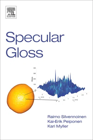 eBook - PDF
- Raimo Silvennoinen, Kai-Erik Peiponen, Kari Myller(Authors)
- 2010(Publication Date)
- Elsevier Science(Publisher)
Chapter 2 LIGHT REFLECTION FROM IDEAL SURFACE The spectrum of electromagnetic radiation ranges from zero energy up to high energies corresponding to gamma rays. In that sense, the wavelength range of visible light is rather narrow. Nevertheless, this short range of visible light is crucial because it defines the spectral window of a human eye. Hence, much of the assessment of quality of various objects, such as indus-trial products, is based on purely visual inspection of the objects. We can detect the shape and colour of an object and estimate local changes of such attributes. One important factor that helps us to estimate the qual-ity of smooth and rough surfaces is the specular gloss. For instance, illumination of a planar mirror or a win-dow by a torch results in light reflection in specular direction (mirror reflection). Mirror surface is smooth and therefore resembles an ideal surface that is usu-ally exploited in the development of laws of geometric optics. The concept of an ideal surface constitutes also the fundamental assumption in wave optics as concerns the reflection of light from the interface between two media or a stack of layers. In this chapter, we deal with the light interaction with an ideally smooth sur-face. We introduce the basic concepts that are needed in the description of the light propagation and light interaction with media. 6 Specular Gloss 2.1. Electromagnetic theory of light waves 2.1.1. Wave equation It is well known that the radio waves have been for a long time used for transmission of information from one place to another. During the last decades, light waves in the form of pulses have been exploited in telecommunication through optical fibres, thanks to the development of LEDs and lasers. Let us start by considering one-dimensional (1-D) wave motion. Note that in some cases, one dimensiona-lity means that 2-D or 3-D wave motion can be described only with one spatial coordinate. eBook - PDF
- James Shipman, Jerry Wilson, Charles Higgins, Bo Lou, James Shipman(Authors)
- 2020(Publication Date)
- Cengage Learning EMEA(Publisher)
Cengage Learning reserves the right to remove additional content at any time if subsequent rights restrictions require it. 180 Chapter 7 ● Optics and Wave Effects Figure 7.16 Spherical Mirror Geometry A spherical mirror is a section of a sphere with a center of curvature C. The focal point F is halfway between C and the vertex V. The distance from V to F is called the focal length f. The distance from C to V or to a point on the sphere is the radius of curvature R (the radius of the sphere). And R 5 2f, or f 5 R/2. C F Radius of curvature R Mirror Principal axis V f The inside surface of a spherical section is said to be concave (as though looking into a recess or cave), and when it has a mirrored surface, it is a concave (converging) mirror. The reason for “converging” is illustrated in ●● Fig. 7.17a. Reflecting light rays parallel to the principal axis converge and pass through the focal point. The rays are “focused” at the focal point. (Off-axis parallel rays converge in the focal plane.) Similarly, the outside surface of a spherical section is said to be convex, and when it has a mirrored surface, it is a convex (diverging) mirror. Parallel rays along the principal axis are reflected in such a way that they appear to diverge from the focal point (Fig. 7.17b). In regard to reverse ray tracing, light rays coming to the mirror from the surround- ings are made parallel, and an expanded field of view is seen in the diverging mirror. Diverging mirrors are used on side mirrors of cars and trucks to give drivers a wider rear view of traffic and in stores to monitor aisles (Fig. 7.17c). Ray Diagrams The images formed by spherical mirrors can be found graphically using ray diagrams. An arrow is commonly used as the object, and the location and size of the image are determined by drawing two rays: Figure 7.17 Spherical Mirrors (a) Rays parallel to the principal axis of a concave or converging spherical mirror converge at the focal point. eBook - PDF
- Charles A. Bennett(Author)
- 2022(Publication Date)
- Wiley(Publisher)
For most purposes, 𝜃 = 0.1 rad or about 5 ∘ is small enough. Figure 4.7 An optics table uses precisely aligned holes to mount optical elements along a well-defined optical axis. Source: Boris Starosta/Science Source. 4.3 Reflection and Refraction at a Spherical Surface 113 (a) (b) M s p θ 1 θ i s i s o R h A θ a B θ b C θ c θ 2 Figure 4.8 (a) A light ray emanating from source s reflects at a spherical surface and passes through point P. (b) A triangle illustrating the law of sines. Side a is opposite angle 𝜃 a , and so on. 4.3.2 Spherical Reflecting Surfaces In this section, we use the paraxial approximation to locate images formed by spherical reflecting surfaces. Figure 4.8 shows a concave spherical reflecting surface with center of curvature located at the point R. The source point s is located on the optical axis, which coincides with the axis of symmetry for the spherical surface. An arbitrary ray leaving s intersects the spherical surface at M with an angle of incidence given by 𝜃 i , measured relative to the radius line that defines the normal to the surface. The reflected ray passes through a point p that is also located on the optical axis. The surface can form an image if all rays it receives from s are reflected through p. Let the distance along the optical axis from s to the reflecting surface be the object distance s o and the distance along the optical axis from p to the reflecting surface be the image distance s i . The law of sines 6 is illustrated in Figure 4.8(b): sin 𝜃 a A = sin 𝜃 b B = sin 𝜃 c C (4.9) Applying the law of sines to triangle sRM in Figure 4.8 gives sin 𝜃 i s o − R = sin 𝜃 1 R (4.10) Similarly, for triangle RpM, we have sin 𝜃 i R − s i = sin ( 180 − 𝜃 2 ) R (4.11) Combining Equations 4.10 and 4.11 gives sin 𝜃 1 sin 𝜃 2 = R − s i s o − R (4.12) According to this result, the value of s o would depend on the values of 𝜃 1 and 𝜃 2 , so it would not be true that all reflected rays pass through a single point p. eBook - PDF
- Leonid Brekhovskikh(Author)
- 2012(Publication Date)
- Academic Press(Publisher)
CHAPTER IV REFLECTION AND REFRACTION OF SPHERICAL WAVES T H E theory of the reflection and refraction of spherical waves has become of immediate importance as a result of the intensive development of radiophysics and acoustics during the last few decades. All of the fundamental problems which arose earlier in optics were solved through the use of plane wave representations. Even in optical phenomena involving diverging waves, it was always possible to consider the field only at distances at which the radius of curvature of the wave front was large compared with the wavelength. Under these conditions, a spherical wave could be considered plane, over a limited portion of the wave front. Only in radiophysics and acoustics do we find conditions under which the distances between the reflecting objects (in particular, interfaces between media) and the radiator are comparable with the wavelength. These circumstances explain the fact t h a t a complete theory of the reflection and refraction of spherical waves was created only during the last two decades, whereas the theory of the reflection and refraction of plane waves had already been developed by Fresnel. The problem we are considering was first studied by Sommerfeld, 1 95 who investigated the field of a variable electric dipole located on a plane interface between two media. Later, fundamental investigations were performed by Weil, 2 07 Fok (see Ref. 24, Chap. 23, edited by Fok) and Leontovich. 57 In the presentation below, I will follow principally m y own w o r k . 3 2 ' 33 Using the method developed in these articles, we shall be able to apply a unified point of view to problems which until now have been studied by various methods (for example, a source located at an interface, a raised source, moderate and high conductivity of one of the media, acoustical case, etc.). We shall use the same method to solve the problem of the refraction of spherical waves.
Index pages curate the most relevant extracts from our library of academic textbooks. They’ve been created using an in-house natural language model (NLM), each adding context and meaning to key research topics.