Physics
Ray Tracing Mirrors
Ray tracing mirrors involves tracing the path of light rays as they reflect off mirrors. This process allows for the prediction of the location and properties of the reflected image. By applying the laws of reflection, such as the angle of incidence being equal to the angle of reflection, ray tracing mirrors can be used to understand and analyze optical systems.
Written by Perlego with AI-assistance
Related key terms
1 of 5
11 Key excerpts on "Ray Tracing Mirrors"
 eBook - PDF
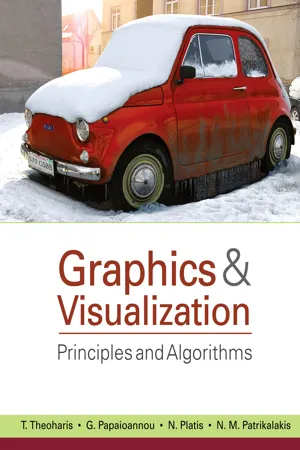
Graphics and Visualization
Principles & Algorithms
- T. Theoharis, Georgios Papaioannou, Nikolaos Platis, Nicholas M. Patrikalakis(Authors)
- 2008(Publication Date)
- A K Peters/CRC Press(Publisher)
Electromagnetic wave transmission theory, but most of all geomet-rical optics and the laws of reflection and refraction, provided the framework for 529 530 15. Ray Tracing the study of light-object interaction in the physics domain, a long time before the inception of ray tracing as a computer algorithm in the early 1980s. Direct real-time rendering in its pure form disassociates the color and shading of a particular surface area from the existence of other objects in the same envi-ronment. Shadows and reflected/refracted light on surfaces need to be simulated or approximated separately and fused as color information in the local illumina-tion model that is used during scan conversion. Ray tracing, on the other hand, integrates all calculations that involve the specular transmission of light in one single and elegant recursive algorithm, the recursive ray tracing algorithm (see Section 15.3). 15.2 Principles of Ray Tracing Let us first look at how light that emanates from a single point light source is transmitted through space. In Figure 15.1, a glass cube resting on a checkered surface is lit by a single point light source. Light emanates from the location of the light source toward every direction, following an infinite number of straight paths until it hits a surface. On the interface between two different solids, 1 light is diffusely scattered and specularly reflected or refracted. In this particular example, the checkered surface has no mirror-like qualities or transparency, so light leaving this surface is esti-mated by using a local illumination model, such as the Blinn model (see Chap-ter 12). According to the surface’s BRDF, part of the specularly and diffusely reflected light is directly received by the observer, unless there is no clear line of sight between this point and the center of projection of the observer.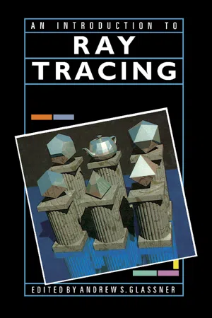 eBook - PDF
- Andrew S. Glassner(Author)
- 1989(Publication Date)
- Morgan Kaufmann(Publisher)
Notice that if you're looking into a mirror, you can probably see some objects in the mirror that you can't see directly. The photons are leaving the light source, hitting those objects, then hitting the mirror, and eventually finding your eyes. We've just been ray tracing. We followed (or traced) the path of a photon (or ray of light) as it bounced around the scene. More specifically, we've been forward ray tracing] that is, we followed photons from their origin at the light and into the scene, tracing their path in a forward direction, just as the photons themselves would have travelled it. 2.2 Forward Ray Tracing and Backward Ray Tracing The technique of forward ray tracing described above is a first approximation to how the real world works. You might think that simulating this process directly would be a good way to make pictures, and you would be pretty much correct. But there is a problem with such a direct simulation, and that's the amount of time it would take to produce an image. Consider that each light source in a scene is generating possibly millions of photons every second, where each photon is vibrating at a slightly different frequency, going in a 8 An Overview of Ray Tracing slightly different direction. Many of these photons hit objects that you would never see at all, even indirectly. Other just pass right out of the scene, for example by flying out through à window. If we were to try to create a picture by actually following photons from their source, we would find a depressingly small number of them ever hit the screen with any appreciable intensity. It might take years just to make one dim picture! The essential problem is not that forward ray tracing is no good, but rather that many of the photons from the light source play no role in a given image. Computationally, it's just too expensive to follow useless photons. The key insight for computational efficiency is to reverse the problem, by following the photons backwards instead of forwards.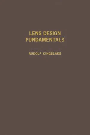 eBook - PDF
- Rudolf Kingslake(Author)
- 2012(Publication Date)
- Academic Press(Publisher)
C H A P T E R 2 Meridional Ray Tracing I. INTRODUCTION It is reasonable to assume that anyone planning to study lens design is already familiar with the basic facts of geometrical and physical optics. However, there are a few points that should be stressed to avoid confusion or misunderstanding on the part of the reader. A. OBJECT AND IMAGE All lens design procedures are based on the principles of geometrical optics, which assumes that light travels along rays that are straight in a homogeneous medium. Light rays are refracted or reflected at a lens or mirror, whence they proceed to form an image. Due to the inherent proper-ties of refracting and reflecting surfaces and the dispersion of refracting media, the image of a point is seldom a perfect point but is generally afflicted with aberrations. Further, owing to the wave nature of light, the most perfect image of a point is always, in fact, a so-called Airy disk, a tiny patch of light of the order of a few wavelengths in diameter surrounded by decreasingly bright rings of light. It should be remembered that both objects and images can be either real or virtual. The object presented to the first surface of a system is, of course, always real. The second and following surfaces may receive converg-ing or diverging light, indicating respectively a virtual or real object for that surface. It must never be forgotten that in either case the refractive index to be applied to the calculation is that of the space containing the entering rays at the surface under consideration. This is known as the object space for that surface. Similarly, the space containing the rays emerging from a surface is called the image space, and real or virtual images are considered to lie in this space. Because of the existence of virtual objects and virtual images we must regard the object and image spaces as overlapping to infinity in both directions. B. THE LAW OF REFRACTION The well-known Snell's law is generally written ri sin L = n sin / 19 eBook - PDF
- John D. Cutnell, Kenneth W. Johnson, David Young, Shane Stadler(Authors)
- 2021(Publication Date)
- Wiley(Publisher)
788 CHAPTER 25 The Reflection of Light: Mirrors 25.1 Wave Fronts and Rays Mirrors are usually close at hand. It is difficult, for example, to put on makeup, shave, or drive a car without them. We see images in mirrors because some of the light that strikes them is reflected into our eyes. To discuss reflection, it is necessary to introduce the concepts of a wave front and a ray of light, and we can do so by taking advantage of the familiar topic of sound waves (see Chapter 16). Both sound and light are kinds of waves. Sound is a pressure wave, whereas light is electromagnetic in nature. However, the ideas of a wave front and a ray apply to both. Consider a small spherical object whose surface is pulsating in sim- ple harmonic motion. A sound wave is emitted that moves spherically outward from the object at a constant speed. To represent this wave, we draw surfaces through all points of the wave that are in the same phase of motion. These surfaces of constant phase are called wave fronts. Figure 25.1 shows a hemispherical view of the wave fronts. In this view they appear as concentric spherical shells about the vibrat- ing object. If the wave fronts are drawn through the condensations, The Cloud Gate sculpture, created by artist Anish Kapoor, is affectionately known as ‟The Bean,” due to its curved shape. Its highly polished stainless steel surface reflects the light around it, forming an image here of the buildings in the Chicago skyline. The reflection of light and the properties of the images formed by this and other kinds of mirrors will be the focus of this chapter. rlobes/Pixabay LEARNING OBJECTIVES After reading this module, you should be able to... 25.1 Relate wave fronts and rays. 25.2 Apply the law of reflection to plane mirrors. 25.3 Describe image formation by a plane mirror. 25.4 Calculate the focal length of a spherical mirror. 25.5 Perform ray tracing for spherical mirrors. 25.6 Use the mirror and magnification equa- tions to solve problems.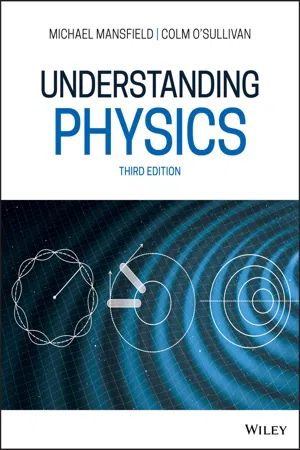 eBook - ePub
- Michael M. Mansfield, Colm O'Sullivan(Authors)
- 2020(Publication Date)
- Wiley(Publisher)
23 Geometrical opticsAIMS
- to introduce the ray model and to ascertain how it explains the phenomena of reflection and refraction
- to describe how the ray model explains image formation in mirrors and lenses
- to explain the operation of certain optical instruments
- to discuss dispersion of light in transparent media
23.1 The ray model: geometrical optics
Consider a geometrical area which is a long way from a source of waves as shown shaded in Figure 23.1 . The spherical wavefronts that pass through such an area emerge almost parallel. These waves, therefore, can be approximated to plane waves and, in the limit of the shaded area in Figure 23.1 becoming very small, may be considered to travel in an infinitesimally narrow beam.A ray of light as the limit of a very narrow beam of plane waves.Figure 23.1Rays from a point source of light; the figure shows just a few of the infinite number of such rays envisaged in the ray model.Figure 23.2In such a situation the energy of the wave may be considered to propagate in straight lines, as it does in the case of particles. This model of wave propagation leads to the concept of a light ray in geometrical optics, the ray being always perpendicular to the wavefront. Thus, a point source of light may be considered to be a source of rays emanating radially from the source in all directions (Figure 23.2 eBook - PDF
- Michael Tammaro(Author)
- 2019(Publication Date)
- Wiley(Publisher)
More generally, reflection is part of a branch of physics called optics, which involves the propagation of light and how it interacts with matter. Wave Fronts and Rays Consider the waves that are created when a stone is dropped into a still body of water, as illustrated in Animated Figure 25.1.1. The disturbance creates a series of concentric ripples that propagate outward from the source. If we draw lines connecting all points on a wave peak, we form the yellow circles. These circles are called the wave fronts. (Strictly speaking, wave fronts are lines connecting points of any particular phase—not necessarily wave peaks, but the distinction is not important here.) The black lines are called rays. They are perpendicular to the wave fronts and point in the direction of the wave velocity. The wave fronts can be thought of as physical parts of the wave (e.g., the wave peaks), but the imaginary rays are actually more helpful in describing wave propaga- tion. Specifically, the physical laws governing reflection (and other optical phenomena) are more easily stated in terms of what happens to the rays than what happens to the wave fronts. Animated Figure 25.1.1 uses water waves to illustrate these concepts, but wave fronts and rays can also be used to characterize light waves. A laser creates a narrow, directional beam of light, which serves as a good model of a light ray. 25.1 WAVE FRONTS, RAYS, AND REFLECTION Learning Objective Animated Figure 25.1.1 A stone dropped into a pond creates a series of outward-propagating wave fronts. The rays are perpendicular to the fronts and parallel to the wave velocity. I N T E R A C T I V E F E A T U R E Now consider a source of waves in three dimensions, like a light bulb or a sound speaker. The wave fronts are now concentric spheres (instead of circles), and the rays propagate radially outward from the source. Figure 25.1.2(a) illustrates the situation near the source, eBook - PDF
- John D. Cutnell, Kenneth W. Johnson, David Young, Shane Stadler, Heath Jones, Matthew Collins, John Daicopoulos, Boris Blankleider(Authors)
- 2020(Publication Date)
- Wiley(Publisher)
CHAPTER 25 The reflection of light: mirrors LEARNING OBJECTIVES After reading this module, you should be able to: 25.1 relate wave fronts and rays 25.2 apply the law of reflection to plane mirrors 25.3 describe image formation by a plane mirror 25.4 calculate the focal length of a spherical mirror 25.5 perform ray tracing for spherical mirrors 25.6 use the mirror and magnification equations to solve problems. INTRODUCTION Amateur and professional astronomers benefit from the light gathered to create images formed by the most versatile telescopes ever built — reflectors. This chapter discusses how images are created by the reflection of light from plane and spherical mirrors. 25.1 Wave fronts and rays LEARNING OBJECTIVE 25.1 Relate wave fronts and rays. FIGURE 25.1 A hemispherical view of a sound wave emitted by a pulsating sphere. The wave fronts are drawn through the condensations of the wave, so the distance between two successive wave fronts is the wavelength . The rays are perpendicular to the wave fronts and point in the direction of the velocity of the wave. l Wave fronts Pulsating sphere Rays Mirrors are usually close at hand. It is difficult, for example, to put on makeup, shave, or drive a car without them. We see images in mirrors because some of the light that strikes them is reflected into our eyes. To discuss reflection, it is necessary to introduce the concepts of a wave front and a ray of light, and we can do so by taking advantage of the familiar topic of sound waves (see chapter 16). Both sound and light are kinds of waves. Sound is a pressure wave, whereas light is electromagnetic in nature. However, the ideas of a wave front and a ray apply to both. Consider a small spherical object whose surface is pulsating in simple harmonic motion. A sound wave is emitted that moves spherically outwards from the object at a constant speed. To represent this wave, we draw surfaces through all points of the wave that are in the same phase of motion. eBook - PDF
- John D. Cutnell, Kenneth W. Johnson, David Young, Shane Stadler(Authors)
- 2015(Publication Date)
- Wiley(Publisher)
We can analyze the image produced by either concave or convex mirrors by using a graphical method called ray tracing. This method is based on the law of reflection and the notion that a spherical mirror has a center of curva- ture C and a focal point F. Ray tracing enables us to find the location of the image, as well as its size, by taking advantage of the following fact: paraxial rays leave from a point on the object and intersect, or appear to intersect, at a corresponding point on the image after reflection. Concave Mirrors Three specific paraxial rays are especially convenient to use in the ray-tracing method. Figure 25.17 shows an object in front of a concave mirror, and these three rays leave from a point on the top of the object. The rays are labeled 1, 2, and 3, and when tracing their paths, we use the following reasoning strategy. Reasoning Strategy Ray Tracing for a Concave Mirror Ray 1. This ray is initially parallel to the principal axis and, therefore, passes through the focal point F after reflection from the mirror. Ray 2. This ray initially passes through the focal point F and is reflected parallel to the principal axis. Ray 2 is analogous to ray 1, except that the reflected, rather than the incident, ray is parallel to the principal axis. Ray 3. This ray travels along a line that passes through the center of curvature C and follows a radius of the spherical mirror; as a result, the ray strikes the mirror perpendicularly and reflects back on itself. Sodium unit and engine Courtesy Sandia National Laboratories Question 5 Figure 25.17 The rays labeled 1, 2, and 3 are useful in locating the image of an object placed in front of a concave spherical mirror. The object is represented as a vertical arrow. C Object 1 F C F 2 C F 3 eBook - PDF
- John D. Cutnell, Kenneth W. Johnson, David Young, Shane Stadler(Authors)
- 2015(Publication Date)
- Wiley(Publisher)
The rays are perpendicular to the wave fronts and point in the direction of the velocity of the wave. 700 Chapter 25 | The Reflection of Light: Mirrors 25.2 | The Reflection of Light Most objects reflect a certain portion of the light falling on them. Suppose that a ray of light is incident on a flat, shiny surface, such as the mirror in Figure 25.3. As the drawing shows, the angle of incidence u i is the angle that the incident ray makes with respect to the normal, which is a line drawn perpendicular to the surface at the point of incidence. The angle of reflection u r is the angle that the reflected ray makes with the normal. The law of reflection describes the behavior of the incident and reflected rays. When parallel light rays strike a smooth, plane surface, such as the ones in Figure 25.4a, the reflected rays are parallel to each other. This type of reflection is one example of what is known as specular reflection and is important in determining the properties of mirrors. Most surfaces, however, are not perfectly smooth, because they contain irregularities the sizes of which are equal to or greater than the wavelength of the light. The law of reflection applies to each ray, but the irregular surface reflects the light rays in various directions, as Figure 25.4b suggests. This type of reflection is known as diffuse reflection. Common surfaces that give rise to diffuse reflection are most papers, wood, nonpolished metals, and walls covered with a “flat” (nongloss) paint. The physics of digital movie projectors and micromirrors. A revolution in digital tech- nology is occurring in the movie industry, where digital techniques are now being used to produce films. Until recently, films have been viewed primarily by using projectors that shine light directly through a strip of film containing the images. eBook - PDF
- John D. Cutnell, Kenneth W. Johnson, David Young, Shane Stadler(Authors)
- 2018(Publication Date)
- Wiley(Publisher)
LEARNING OBJECTIVES After reading this module, you should be able to... 25.1 Relate wave fronts and rays. 25.2 Apply the law of reflection to plane mirrors. 25.3 Describe image formation by a plane mirror. 25.4 Calculate the focal length of a spherical mirror. 25.5 Perform ray tracing for spherical mirrors. 25.6 Use the mirror and magnification equations to solve problems. Digital Vision/Getty Images CHAPTER 25 The Reflection of Light: Mirrors The image of the zebras drinking at the waterhole is produced when light reflects from the plane surface of the water, which acts as a mirror. This chapter discusses the images formed by the reflection of light from plane and spherical mirrors. 25.1 Wave Fronts and Rays Mirrors are usually close at hand. It is difficult, for example, to put on makeup, shave, or drive a car without them. We see images in mirrors because some of the light that strikes them is reflected into our eyes. To discuss reflection, it is necessary to introduce the concepts of a wave front and a ray of light, and we can do so by taking advantage of the familiar topic of sound waves (see Chapter 16). Both sound and light are kinds of waves. Sound is a pressure wave, whereas light is electromagnetic in nature. However, the ideas of a wave front and a ray apply to both. Consider a small spherical object whose surface is pulsating in simple harmonic motion. A sound wave is emitted that moves spherically outward from the object at a constant speed. To represent this wave, we draw surfaces through all points of the wave that are in the same phase of motion. These surfaces of constant phase are called wave fronts. Figure 25.1 shows a hemispherical view of the wave fronts. In this view they appear as concentric spherical shells about the vibrating object. If the wave fronts are drawn through the condensations, or crests, of the sound wave, as they are in the picture, the distance between adjacent wave fronts equals the wavelength . No longer available |Learn more
Physics for Scientists and Engineers
Foundations and Connections, Extended Version with Modern Physics
- Debora Katz(Author)
- 2016(Publication Date)
- Cengage Learning EMEA(Publisher)
Ray Diagrams We used a crude ray diagram when we studied the camera obscura. Now we describe the elements needed to sketch a ray diagram that can be used to find the image formed by a plane mirror (Fig. 37.15): 1. A thick line representing the mirror seen edge-on. Light totally reflects from the thin layer on the front of the mirror. Assume an observer and an object are in front of the mirror. (Usually, the front side is shown on the left, but that is not necessary and is sometimes inconvenient.) It is not normally necessary to represent the observer. 2. An arrow representing the object. 3. A small number of emitted rays (usually four or fewer) coming from key points on the object, such as the tip and base of the arrow. 4. Reflected rays. For each emitted ray, use the law of reflection to draw the reflected ray. 5. An arrow representing the image. Consider two rays emitted from a single point, such as from the tip or the base of the arrow, and find the place where their reflected rays cross or would appear to cross. Because these rays were emitted from a single point, the image of that point is formed where the reflected rays cross (or seem to cross). Use this crossing point to sketch the image at that loca- tion. (In Figures 37.3 and 37.4, we considered rays emitted from two separate points of the object, so they do not cross to form a point on the image.) Virtual and Real Images In Figure 37.15, the two rays emitted from the tip of the object arrow are reflected by the mirror. These reflected rays enter the observer’s eye without crossing, and the hu- man brain assumes the rays are not bent. So, in effect, the brain traces these rays back along two straight lines that meet at an imaginary point behind the mirror, but there is no light behind the mirror. (Your bathroom mirror is probably hanging on a wall.) Nevertheless, your brain interprets the point where these rays appear to meet as the location of the image.
Index pages curate the most relevant extracts from our library of academic textbooks. They’ve been created using an in-house natural language model (NLM), each adding context and meaning to key research topics.