Technology & Engineering
CAD to CAM
CAD (Computer-Aided Design) to CAM (Computer-Aided Manufacturing) refers to the seamless integration of design and manufacturing processes using digital technology. CAD software is used to create detailed 2D or 3D models of products, which are then translated into instructions for CAM software to automate the manufacturing process. This integration streamlines production, reduces errors, and enhances efficiency in the manufacturing industry.
Written by Perlego with AI-assistance
Related key terms
1 of 5
11 Key excerpts on "CAD to CAM"

- Winston A. Knight, Geoffrey Boothroyd(Authors)
- 2019(Publication Date)
- CRC Press(Publisher)
12.2 SCOPE OF CAD/CAM Computer-aided design is the use of computer systems to facilitate the creation, modification, analysis, and optimization of a design [1]. In this context the term computer system means a combination of hardware and software. Computer-aided manufacturing is the use of a computer system to plan, manage, and control the operation of a manufacturing plant. An appreciation of the scope of CAD/CAM can be obtained by considering the stages that must be completed in the design and manufacture of a product, as illustrated by the product cycle shown in Figure 12.1. The inner loop of this figure includes the various steps in the product cycle, and the outer loop shows some of the functions of CAD/CAM superimposed on the product cycle. Based on market and customer requirements, a product is conceived, which may well be a modification of previous products. This product is then designed 402 Fundamentals of Machining and Machine Tools in detail, including any required design analysis, and geometric models and parts lists are prepared. Subsequently, the various components and assemblies are planned for production, which involves the selection of sequences of processes and machine tools and the estimation of cycle times, together with the determi-nation of process parameters, such as feeds and speeds for machining operations. When the product is in production, scheduling and control of manufacture take place, and the order and timing of each manufacturing step for each component and assembly is determined to meet an overall manufacturing schedule. The actual manufacturing and control of product quality then takes place according to the schedule and the final products are delivered to the customers. Computer-based procedures have been developed to facilitate each of these stages in the product cycle, and these are shown in the outer loop of Figure 12.1. Computer-aided design and drafting techniques have been developed.
- Winston A. Knight, Geoffrey Boothroyd(Authors)
- 2019(Publication Date)
- CRC Press(Publisher)
12 Computer-Aided Manufacturing12.1 Introduction
Computers are used extensively in the scientific and commercial fields. Computer systems are now available that combine high computing power with high reliability, small size, and low cost, making their use viable in increasing ranges of applications. These computer developments have made possible the rapid performance of tasks that are complicated and time consuming to do manually. Computers can be programmed to carry out complex calculations and to process and store large amounts of data with high speed and efficiency. As a result, computers have become extensively used in both design and manufacture, leading to the concepts of computer-aided design (CAD) and computer-aided manufacture (CAM) or CAD/CAM for short. The objective is to increase the efficiency of all aspects of design and manufacture and to integrate these activities by means of shared databases, together with automatic data transfer between the various design and planning activities to be carried out. In this chapter only those aspects of CAD/CAM concerned with the technological aspects of machine tool application are considered in detail; in particular, process planning and numerical control (NC) programming applications are discussed. Details of other CAD/CAM applications can be found in a variety of publications [1 ,2 ,3 ,4 ]. Before proceeding with details of computer-aided process planning and NC processing systems, an outline of the scope of CAD/CAM applications will be given.12.2 Scope of CAD/CAM
Computer-aided design is the use of computer systems to facilitate the creation, modification, analysis, and optimization of a design [1 ]. In this context the term computer system means a combination of hardware and software. Computer-aided manufacturing is the use of a computer system to plan, manage, and control the operation of a manufacturing plant. An appreciation of the scope of CAD/CAM can be obtained by considering the stages that must be completed in the design and manufacture of a product, as illustrated by the product cycle shown in Figure 12.1 eBook - ePub
- Edward H. Smith(Author)
- 2013(Publication Date)
- Butterworth-Heinemann(Publisher)
A satisfactory implementation of CAD/CAM may be crucial to the future success of a company. CAD/CAM installations need careful planning and management if they are to achieve the desired results.5.1.7.1 People, methods, organization and the technology
CAD/CAM technology affects three aspects of a company, and each must be addressed during the implementation.People In many other applications of computer technology the direct involvement of the users with the system is minimal. However, CAD/CAM systems actively involve the users. This is because the systems, although complete in themselves, can only provide a set of tools to do the work, and hence must rely on the users to apply them to the job in hand in an appropriate way.Methods CAD/CAM frequently results in changes to the company’s working methods. Although it often happens that an existing process is merely computerized, in order to reap the benefits of the technology it is sometimes necessary to change entirely the way in which a job is tackled.Organization The changes as a result of CAD/CAM often embrace several different areas within the organization. The complete integration of these areas may be necessary to enable the company to gain all the advantages of the CAD/ CAM installation.In order for the system to be effective, it frequently relies on the engineering staff who are to use the system becoming fully conversant with it. It also depends upon the company understanding the best way of applying the technology to its product process and exploiting it to advantage.5.1.7.2 System Implementation
The initial implementation of CAD/CAM in a company can be treated as a two-stage process. The first step is the installation and system introduction. This is followed by a period of system tailoring which may involve the development of specialist system features, together with appropriate software enhancements.Introducing the system eBook - ePub
- D.V. Rosato, D.V. Rosato(Authors)
- 2003(Publication Date)
- Elsevier Science(Publisher)
5COMPUTER-AIDED DESIGN
Technology overview
Computer technology requires a completely different methodology of engineering design. It has revolutionized the speed and efficiency of the plastic design functions. The more the entire design function is studied, the more repetitive tasks are uncovered in that function. The computer’s ability to perform these tasks untiringly and with blazing speed is the basis for these productivity gains.The computer continues to provide the engineer with the means to simplify and more accurately develop a design timewise and costwise. It provides a better understanding of the operating requirements for a product design, resulting in maximizing the design efficiency in meeting product requirements. The computer is able to convert a design into a fabricated product providing a faster manufacturing startup. Other benefits resulting from the computer technology include (1) ease of developing and applying new innovative design ideas, (2) fewer errors in drawings; (3) good communications with the fabricator, (4) improved manufacturing accuracy; and (5) a faster response to market demand.Many of the individual tasks within the overall design process can be performed using a computer. As each of these tasks is made more efficient, the efficiency of the overall process increases as well. The computer is suited to aid the designer by incorporating customer inputs, problem definitions, evaluations, and final product designs.Computer-aided design (CAD) uses the mathematical and graphic-processing power of the computer to assist the mechanical engineer in the creation, modification, analysis, and display of designs. Many factors have contributed to CAD technology becoming a necessary tool in the engineering world, such as the computer’s speed at processing complex equations and managing technical databases. CAD combines the characteristics of designer and computer that are best applicable to the design process. eBook - PDF
- Zhuming Bi, Xiaoqin Wang(Authors)
- 2020(Publication Date)
- Wiley-ASME Press Series(Publisher)
398 Computer Aided Design and Manufacturing part of the program is for all motion statements. The last part of the program resets the tool position and terminates the machining operation. 9.6 Computer Aided Manufacturing APT offers the advantages for manual programming. However, it involves defining part geometries and tool positions that tend to be very error-prone. To address this concern, graphics-based CAM was introduced and became popular in the 1980s. This made it pos- sible to describe part geometry by points, lines, and arcs directly rather than requiring a translation to a text-oriented notation. CAM is driven by the graphic representation of a part to generate NC programs semi-automatically. It can usually be run on workstations or personal computers. There is a need when using CAM to understand the fundamen- tals of CNC programming and machining processes, such as the selection of speeds, feed rates, and feed depths based on the materials, tolerances, and tool specifications. Therefore, CAM needs the users to have some built-in expertise about manufacturing processes. As a powerful computer aided technique, CAM provides the following functionalities: 1. Make standardized tools and materials available from the built-in design libraries. 2. Support the simulation of motion paths of cutting tools. 3. Be capable of editing and optimizing tool paths. 4. Estimate cutting times and machining costs. CAM allows minimum information from users in programming machines for parts. The default settings in CNC programming follow the EIA standards or common practices, espe- cially the following: 1. It is assumed that the tool moves relative to the workpiece no matter what actual motion occurs to the machine tool. Taking as an example of the operations on a shaper, the cutting tool is kept still and the workpiece is moved towards the cutting tool. 2. The positions of the objects are described in a Cartesian coordinate system.
- John Stark(Author)
- 2021(Publication Date)
- CRC Press(Publisher)
In general, young designers (especially those joining the company direct from college), liked using CAD/CAM, perhaps because it relieved them of an apprenticeship in manual drafting to company standards. It was found that they became productive more quickly using CAD/CAM, than if they used manual methods. More experienced designers, however, were initially reluctant to involve themselves in CAD/CAM with its attendant unknowns resulting from changing technology, task, organization, and status. In many cases though, there was a catalytic effect—once one experienced designer started to use CAD/CAM, others joined in.A limited amount of ongoing training was given. This training was necessary not only to teach users to use new functions and new modules, but also to ensure that they did not get into a rut of using the system in a less than optimal way.It has been found that implementation of CAD/CAM involves a wider range of problems than most technical projects. Even when the decision to invest has been taken, a lot of time still has to be spent in convincing people to use CAD/CAM, and a host of organizational and human issues have to be resolved. A major effort has been made to convince middle management that CAD/CAM should be used. These managers, who have committed themselves to producing results by manual methods for a certain date, are often unwilling to take the risk of stepping into the unknown area of CAD/CAM, where they may lack knowledge and control.Problems have also arisen where tasks have moved across traditional company boundaries. On some occasions, it has been found advantageous for one department to carry out work that would previously have been carried out in another part of the company. The necessary reallocation of funds and resources has had to be resolved much higher up the organizational hierarchy. Geometry definition is now a function reporting to the CAD/CAM Manager rather than to the Design Office. Similarly, the NC programming support function which reported previously through the Production Department now reports to the CAD/CAM Manager. In some cases, the power of the CAD/CAM system has made it possible for designers (particularly in tool design) to develop NC tool paths themselves without assistance from NC part programmers.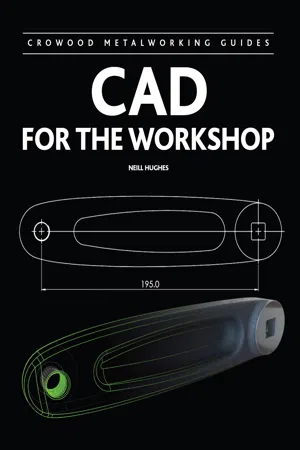 No longer available |Learn more
- Neill Hughes(Author)
- 2013(Publication Date)
- Crowood(Publisher)
There are CAD software products available that enable the modelling and documentation of all these aspects of the design. The next section aims to clarify the role and categories of these products in the context of the above design model types.THE ROLE OF CAD SOFTWARE IN DESIGN AND MANUFACTUREAs already mentioned, originally the acronym CAD stood for ‘computer-aided drafting’. This was back in the early 1980s, when the technology was used to provide an electronic version of a conventional drawing board. That CAD software enabled drawing board tasks to be performed, only with more efficiency in terms of initial drafting, making changes, duplicating entities such as symbols and text notes, and sharing information between people. Now, as also already mentioned, CAD stands for ‘computer-aided design’, implying a wider scope of application than basic drafting. In a commercial context, CAD systems play an essential role in the efficient development of a product, from initial concept creation, design development, through to detail design, drafting (of course) and manufacture.THE DRAWING BOARDPhysical drawing boards are no longer used in commercial engineering design environments, although there are exceptions, of course. Perhaps where a more experienced engineer is reluctant to part with it, or reluctant to embrace different methods, or possibly where a designer finds that larger scale, hand-drafted drawings provide a more effective way of working.Whilst computer-system functionality has revolutionized working methods in design, there is still no substitute for the human-based, creative problem-solving skills. The word ‘aided’ in CAD is significant. CAD is simply a tool to help a designer represent, develop, record and communicate ideas. Many recognized designers acknowledge that the most efficient way to transfer an original idea to a shareable image is by hand sketching. Sir Alex Moulton said in his book From Bristol to Bradford-on-Avon – a Lifetime in Engineering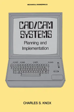 eBook - ePub
- Charles S. Knox, Knox(Authors)
- 2020(Publication Date)
- CRC Press(Publisher)
As an assembly drawing is prepared, the assembly of parts on the screen is a simulated preparation for a parts list. It seems only logical that the part numbers, quantity, and other necessary data be entered at this time. In the same manner, the time to enter data for the item master is while piece parts needed for an assembly are being drawn. The coordination of these events will increase the productivity of engineering with a corresponding decrease in paper flow and volume.We often find that the engineer works for the computer rather than the opposite. Consequently, only when final documentation has been approved does engineering data enter the computer system. CAD/CAM will force a change to this concept simply because it is more practical and economical to put the crudest of ideas in the form of drawings and other data into the computer at the initial design concept. Thus when discussing the bill of material we will emphasize the concept of different levels of documentation integrity.DESIGN STANDARDSDesign standards are often difficult to define. Most engineers still consider design to be a creative process. An analysis of most manufacturing concerns would find, as mentioned previously, a good portion of design is copying and extrapolating old designs. No matter how much or how little this occurs, standards are important to gain consistency in manufacturing, costing, and inspecting the product. Engineering departments have, perhaps, allowed the designer, engineer, and drafter too much license to be different under the guise of creativity. Fortunately, CAD/CAM systems allow storage and portrayal of practical standards for design. The comparatively trivial notions of arrowheads and scribe lines set to national standards have already been determined, so they need not be checked each time a drawing is made. What shall we do about the actual design configuration?Several companies have initiated, in one form or another, information called producibility tips. This data is stored by part family in aCAD/CAM system. Data can be stored which tells the engineer the penalties of alternate designs. Figure 53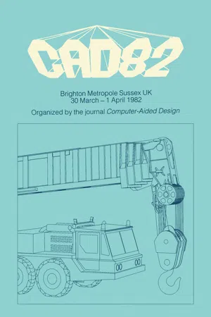 eBook - PDF
CAD82
5th International Conference and Exhibition on Computers in Design Engineering
- Alan Pipes(Author)
- 2017(Publication Date)
- Butterworth-Heinemann(Publisher)
In addition, written documentation may be used, for example, to call up standard parts and define processes. Finally, the tentative layout of the assembly and subassembly drawings can be re-placed by full assembly drawings, derived from the details of each component and the parts lists reflecting the assembly structure produced. At this stage, the product will be transferred to the production department for est-imating, process planning, tooling, manufacturing, assembly and testing. Any CAE system must therefore be capable of assisting in this process over a wide spectrum of company structures and product ranges. 'CAM-X' will now be considered against the background of the design and production engineer's needs. THE 'CAM-X' SYSTEM Introduction The underlying concept of CAM-X is one in which a substantially dedicated computer, connected to a number of workstations, is used to assist in the design and manufac-^· turing processes, through the use of an expandable set of linked software modules. (FIG.1(a), FIG.1(b). Modules are available to allow the designer to define, dimen-45 sion and display views of 2D, 2jD and 3D parts. Families of parts can be directly generated by a parametric pre-processor. From the geometric definition, a solid model can be constructed to assist in visualisation or to permit numerical control tapes to be produced. An Engineering Records Management System (ERMS) provides re-tention and retrieval of information related to products designed on the system. The hub of the software is the Supervisor, which is a computer program located be-tween the host computer operating systems, the modules and the users (FIG.2.) It controls the flow of data and schedule tasks. Well defined interfaces and protocol between the Supervisor and the individual modules, allows new or improved application programs or hardware to be added and linked. The CAM-X system is based on the Digital Equipment Corporation VAX mini-computer.
- Hamid R. Shafie(Author)
- 2014(Publication Date)
- Wiley-Blackwell(Publisher)
6 Use of CAD/CAM Technology in Custom Abutment ManufacturingJulian Osorio1 and Robert B. Kerstein21 Department of Restorative Dentistry, Division of Graduate and Post Graduate Prosthodontics, Tufts University School of Dental Medicine, Boston, MA2 Private Practice, Boston, MAHistory of Cad/Cam Technology in Prosthetic Dentistry
Computer-aided design (CAD)/computer-aided milling (CAM) technology first appeared in prosthetic dentistry with the introduction of the first CEREC scanning and milling system in 1985 (Siemens AG, Germany) (Calamia 1994; Isenberg and Garber 1994). CEREC is an acronym for “chairside economical restoration of esthetic ceramics.” The first CEREC system photographed the cavity preparation and stored the photograph as a 3-dimensional (3D) digital model. Next, the proprietary software approximated the restoration shape using biogeneric comparisons with the surrounding teeth. The clinician could then refine that model using 3D CAD software, after which an optical scanner controlled a milling machine that carved the actual restoration out of a ceramic block using diamond head cutters. The milled ceramic restoration was then bonded into the tooth using a resin cement.Another early CAD/CAM system was the CELAY system (Mikrona Technologie AG, Switzerland) (Eidenbenz et al. 1994; McLaren and Sorensen 1994). The CELAY system had some advantages over the early CEREC system as it could create all surfaces of a restoration, whereas the earliest CEREC system could not fabricate the occlusal surface. Another advantage was that the CELAY system had the potential to fabricate crowns and short-span bridges utilizing the In-Ceram system (Vita Zahnfabrik, Bad Säckingen, Switzerland) (Eidenbenz et al. 1994). Both the CEREC and CELAY systems could be used for direct and indirect restoration fabrication so the clinician could opt for completing a milled ceramic restoration in a single patient appointment. This is still an attribute of the current day CEREC 3D system. eBook - ePub
- Mike Golio(Author)
- 2017(Publication Date)
- CRC Press(Publisher)
16 Technology Computer Aided DesignPeter A. BlakeyNorthern Arizona University- 16.1 Introduction
- 16.2 An Overview of TCAD
- 16.3 Benefits of TCAD
- 16.4 Limitations of TCAD
- 16.5 The Role of Calibration
- 16.6 Applications of TCAD
- 16.7 Application Protocols
- 16.8 Conclusions
16.1 Introduction
Computer-aided design (CAD) is used in response to complexity in engineering problems. The complexity may be associated with the manipulation and storage of large amounts of relatively simple information; or it may be associated with the interactions of complicated nonlinear physical phenomena. Both types of complexity are encountered in the field of microelectronics. Electronics CAD (ECAD) is used to design new products using an existing semiconductor technology, and technology CAD (TCAD) is used to accelerate the development of new semiconductor technologies. ECAD is able to manage large amounts of relatively simple information, such as the number, size, and locations of the polygons used to define lithographic masks. TCAD predicts the way in which nonlinear process and device physics would impact the performance of proposed technologies. The subject matter of this chapter is TCAD and its application to the development of RF, microwave, and millimeter-wave semiconductor technologies.16.2 An Overview of TCAD
The core tools of technology CAD (TCAD) are process simulators and device simulators. Process simulators predict the structures that result from applying a sequence of processing steps to an initial structure. Device simulators predict the electrical characteristics of specified structures. Process and device simulators are often used in combination to predict the impact of process variations on electrical behavior. The basic flow of information is indicated in Fig. 16.1 .Process and device simulators use numerical techniques to solve mathematical equations that describe the underlying physics of an experiment. They are able to predict the result of experiments, without requiring the experiments to be run. Predictive simulation is useful whenever it is time consuming, expensive, dangerous, or otherwise difficult to run real experiments. In the case of microelectronics development, it is both time consuming and expensive to run real experiments in a semiconductor fab. As a result, it can be cost effective to substitute simulated experiments for some of the real experiments that would otherwise be required by purely empirical development procedures.
Index pages curate the most relevant extracts from our library of academic textbooks. They’ve been created using an in-house natural language model (NLM), each adding context and meaning to key research topics.