Technology & Engineering
FEA Structural Analysis
FEA (Finite Element Analysis) Structural Analysis is a computational method used to predict how a structure will respond to various loading conditions. It involves breaking down a complex structure into smaller, more manageable elements to analyze stress, strain, and deformation. By simulating real-world conditions, FEA helps engineers optimize designs and identify potential failure points in structures.
Written by Perlego with AI-assistance
Related key terms
1 of 5
12 Key excerpts on "FEA Structural Analysis"
 eBook - ePub
- Ansel C. Ugural(Author)
- 2022(Publication Date)
- CRC Press(Publisher)
17 Finite Element Analysis in Design * DOI: 10.1201/9781003251378-20 17.1 Introduction In real design problems, generally, structures are composed of a large assemblage of various members. In addition, the built-up structures or machines and their components involve complicated geometries, loadings, and material properties. Given these factors, it becomes apparent that the classical methods can no longer be used. For complex structures, the designer has to resort to more general approaches of analysis. The most widely used of these techniques is the finite element stiffness or displacement method. Unless otherwise specified, we refer to it as the finite element method (FEM). Finite element analysis (FEA) is a numerical approach and well-suited to digital computers. The method is based on the formulations of a simultaneous set of algebraic equations relating forces to corresponding displacements at discrete preselected points (called nodes) on the structure. These governing algebraic equations, also referred to as force-displacement relations, are expressed in matrix notation. With the advent of high-speed, large-storage capacity digital computers, the FEM gained great prominence throughout industries in the solution of practical analysis and design problems of high complexity. The literature related to the FEA is extensive (e.g., [ 1, 2, 3, 4 and 5 ]). Numerous commercial FEA software programs are available, including some directed at the learning process. Most of the developments have now been coded into commercial programs
- Edward R. Champion(Author)
- 2020(Publication Date)
- CRC Press(Publisher)
3 Fundamentals of FEA 3.1 BASIC CONCEPTS The finite element method is an analytical tool for the performing of stress and vibration analysis, and thermal and fluid flow analysis of systems and structures. A typical analysis using the finite element technique requires the following in-formation: 1. Nodal point spatial locations (geometry) 2. Elements connecting the nodal points 3. Mass properties 4. Boundary conditions or restraints 5. Loading or forcing function details 6. Analysis options This information only directs the user toward the fmal solution for the par-ticular problem in question. The user must, in an intelligent manner, interpret the results and apply the results to the actual system behavior. This is a goal of the application of finite element analysis to practical scientific and engineering problems. Certainly, there are other goals beyond the system behavior. If the user is ad-dressing, for example, a structure of some nature, a goal is to develop an under-standing of the structural integrity of the system. If an optimum design of a structure is wanted, the user can use the fmite element method to examine how a structure (system) responds to design modifications. Furthermore, from a cost 15 16 CHAPTER 3 standpoint, the use of finite element modeling to assess or simulate system test-ing or test results presents a goal of product development cost reduction. Can finite element analysis really be done on personal computers? In review-ing the literature, there appear to be three opinions concerning the use of per-sonal computers and finite element analysis as a unit. The first opinion views the combination as merely a tool with which to learn basic finite element techniques and to solve small problems. The second opinion is that full-featured linear finite element analysis is pos-sible on personal computers. eBook - PDF
Applied Metal Forming
Including FEM Analysis
- Henry S. Valberg(Author)
- 2010(Publication Date)
- Cambridge University Press(Publisher)
Hence, these methods still provide useful information and understanding about the mechanics of metal forming. 14.2 FEM Analysis The first effort to develop the FEM date back to work done in 1941–1942. 2 The method was further developed in the following decades and was provided with a mathematical foundation in 1973. 3 FEM is a numerical technique for finding approx- imate solutions of partial differential equations and integral equations. The method was first applied in structural mechanics and is usually based on an energy princi- ple such as that of virtual work or minimum total potential energy. FEA is today generally used for prediction of stresses and displacements in mechanical objects 14.3 FEM Analysis in Metal Forming 221 and systems, and in other applications. The ability to model a structural system in three dimensions can provide an accurate analysis for almost any structure. Three- dimensional models in general can be produced using common computer-aided design (CAD) packages. FEA allows entire designs to be constructed, refined, and optimized before parts are manufactured. FEA has significantly improved the stan- dard of engineering design and the methodology of the design process in many industrial applications. It has substantially reduced the time required to get prod- ucts from concept level to production line. 14.3 FEM Analysis in Metal Forming In this book, the focus is on the use of FEA in metal forming applications. This new analysis tool has made it possible to analyze a chosen process on the computer rather than using trial and error in the forming machine. Process simulation using FEA has yielded considerable cost and quality improvements in the industry. FEM simulation has become a practical and efficient tool for prediction of performance in industrial forming operations before dies are manufactured. Today, FEA is an extremely effective tool for research and also in industrial applications. eBook - PDF
Control and Dynamic Systems V58: Computer-Aided Design/Engineering (Cad/Cae) Techniques And Their Applications Part 1 of 2
Advances in Theory and Applications
- C.T. Leonides(Author)
- 2012(Publication Date)
- Academic Press(Publisher)
One very important tool to the engineering designer is the Finite Element Meth-od (FEM), which is utilized in many companies in engineering analysis. Finite Element Analysis, or simply FEA, is used for analyzing new designs derived from the engineering design process. FEA IN THE ENGINEERING DESIGN PROCESS 121 The importance of powerful tools for analytical purposes within the engineering design process has long been recognized by researchers within the field of engi-neering design. Based on an idea propounded by N. P. Suh in his book The Prin-ciples of Design [7], the interactions between the synthesis and the analysis acti-vities can be illustrated by a feedback loop. In the engineering design process, the synthesis (a creative activity) is always followed by an analysis (an evaluation activity) of the results obtained. This is illustrated in figure 1. The occurrence of a feedback loop is due to the fact that the results derived from the creative activity have to be checked through analysis and corrected or renewed (new design solution candidate) if discrepancies exist between the definition of the design task and the current design solution candi-date. Figure 1: The synthesis-analysis activities as a feedback loop. In the figure, X denotes the input (design task/specification), YXht output (design solution), G the synthesis capability and Η the analytical ability. This gives a transfer function according to Eq. (1). Y X 1 + GH (1) If the gain of the feedback is much larger than one, Eq. (1) is reduced to: Y X G GH H~ for GH > > 1 (2) The more powerful the analytical ability, the more rapidly the process converges to a (final) design solution. From the results of an exploratory survey in ten major product developing com-panies in Sweden, A. Burman [8] has concluded that the engineering designer 122 Β. BJÄRNEMO ETAL. seldom or never actively participates in finite element based analyses in the en-gineering design process. eBook - PDF
- Yong Bai(Author)
- 2003(Publication Date)
- Elsevier Science(Publisher)
These formulae-based rules were followed by direct calculations of hydrodynamic loads and finite element stress analysis. The Finite Element Methods (FEM) have now been extensively developed and applied for the design of ship and offshore structures. Structural analysis based on FEM has provided results, which enable designers to optimize structural design. The design by analysis approach is now applied throughout the design process. The finite element analysis has been very popular for strength and fatigue analysis of marine structures. In the structural design process, the dimensions and sizing of the structure are 4 Part I Structural Design Principles strengthened, and structural analysis re-conducted until the strength and fatigue requirements are met. The use of FEM technology has been supported by the fast development of computer and information technology. Information technology is widely used in structural analysis, data collection, processing, and interpretation, as well as in the design, operation, and maintenance of ship and offshore structures. The development of computer and information technology has made it possible to conduct a complex structural analysis and process the analysis results. To aid the FEM based design, various types of computer based tools have been developed, such as CAD (Computer Aided Design) for scantling, CAE (Computer Aided Engineering) for structural design and analysis and CAM (Computer Aided Manufacturing) for fabrication. Structural design may also be conducted based on performance requirements such as design for accidental loads, where managing risks is of importance. 1.1.2 Limit-State Design In a limit-state design, the design of structures is checked for all groups of limit-states to ensure that the safety margin between the maximum likely loads and the weakest possible resistance of the structure is large enough and that fatigue damage is tolerable.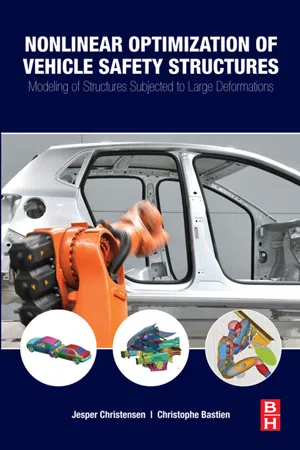 eBook - ePub
Nonlinear Optimization of Vehicle Safety Structures
Modeling of Structures Subjected to Large Deformations
- Jesper Christensen, Christophe Bastien(Authors)
- 2015(Publication Date)
- Butterworth-Heinemann(Publisher)
Chapter | twoNumerical Techniques for Structural Assessment of Vehicle Architectures
Abstract
This chapter addresses three main aspects: introduction to the finite element method (FEM), advanced finite element analysis (FEA), and the application of FEM/FEA to vehicle structures with an emphasis on large deformation/nonlinear and dynamic analysis. The first sections of the chapter are intended to act as a refresher of the basics of FEM, briefly outlining the fundamental equations and principles. The following sections of the chapter are aimed at providing an overview of more complex FEA problems, such as nonlinear and/or dynamic analysis, as often required in connection with vehicle safety structures. The purpose of the final sections of this chapter is to unite Chapter 1 and the initial sections of this chapter into an overview of how FEM/FEA is used for vehicle structural design and analysis, including postprocessing of results, and will form the basis for the remaining chapters of this book.Keywords
finite element method (FEA) finite element analysis (FEA) nonlinear FEA explicit FEA implicit FEA crash analysis crashworthiness durability safetyChapter outline2.1 Introduction to Finite Element Analysis (FEA)522.2 Theory of Elasticity562.3 Elements632.4 Fundamental Explicit and Implicit Finite Element Analysis782.5 Nonlinear Explicit Finite Element Analysis792.6 Explicit FEA Applied to Vehicle Safety Assessment822.7 Contacts932.8 Example Convergence Study of Explicit FEA99References 105Many options exist for assessing the structural (safety) performance of vehicle architectures, including real-world testing, manual calculations, and computer simulations. There are three main parameters that dominate the decision process for the choice of analysis approach to the structural assessment of vehicle architectures: flexibility/versatility, accuracy, and precision. eBook - ePub
Up and Running with Autodesk Inventor Simulation 2011
A Step-by-Step Guide to Engineering Design Solutions
- Wasim Younis(Author)
- 2010(Publication Date)
- Butterworth-Heinemann(Publisher)
CHAPTER 9The Stress Analysis Environment
Publisher Summary
The finite element method (FEM) is a mathematical/computer-based numerical technique for calculating the strength and behavior of engineering structures. Autodesk Inventor— and much other analysis software—is based on the FEM, where, simply, a component is broken down into many small elements. There are three methods within Autodesk Inventor Simulation that can be used to enhance the accuracy of the results: P-refinement, H-refinement, and higher order elements. Autodesk Inventor Simulation is only capable of performing linear analysis, where components have small deformations, under operational loading conditions. On the other hand, nonlinear analysis is typically involved when components are experiencing large deformations and thus component material can deform beyond the elastic limit. This chapter describes static analysis. It is an engineering discipline that determines the stress in materials and structures subjected to static or dynamic forces or loads. The aim of the analysis is usually to determine whether the element or collection of elements, usually referred to as a structure or component, can safely withstand the specified forces and loads. This is achieved when the determined stress from the applied force(s) is less than the yield strength the material is known to be able to withstand.The Finite Element Method (FEM) – an Overview
The finite element method (FEM) is a mathematical/computer-based numerical technique for calculating the strength and behavior of engineering structures. Autodesk Inventor – and much other analysis software – is based on the FEM, where, simply, a component is broken down into many small elements, as shown below.Let's assume that we need to determine the displacement of the component. This displacement (unknown quantity) acts over each element in a predefined manner – with the number and type of elements chosen so that overall distribution through the component is sufficiently approximated. This distribution across each element is commonly presented by a polynomial – whether it is linear, quadratic, or even cubic. It is important to note that FEM is always an approximation of the actual component and by its very nature will have errors due to discretization – particularly around curved boundaries (as shown above) or geometrically complex components. eBook - PDF
- Zhuming Bi, Walter D. Pilkey, Deborah F. Pilkey(Authors)
- 2020(Publication Date)
- Wiley(Publisher)
In this section, Solidworks is used as the vehicle to illustrate how a commercial software tool can be adopted to fulfill various tasks involved in the preprocessing, processing, and postprocessing of FEA. Fig. 6.24 gives an overview of the mappings between available functional modules in Solidworks and major tasks involved in FEA modelling. No matter what type of software architecture (i.e., structural, procedural, or object-oriented architecture) is adopted in programming, graphic user interfaces (GUIs) of a commercial FEA 550 FINITE ELEMENT ANALYSIS (FEA) FOR STRESS ANALYSIS Create CAD Assign material properties Assemble parts into as assembly Simulation based design optimization Verification of solutions Validation of Design and Analysis Scope for validation Scope for verification CAD Modeling Mesh Tools Materials Tools Analysis Models Parametric Study Loading Tools Restraints Tools Contact Tools Results Tools Solvers PROPROCESSING PROCESSING POST-PROCESSING Isolate object and application from environment Discretize solid object(s) into nodes and elements Develop element models and assemble them into a system model Define boundary conditions and loads, and modify system models and load vectors based on boundary conditions Solve system model Evaluate dependent variables and scales, visualize or analyze results Figure 6.24 Solidworks simulation for FEA (Bi 2018). FINITE ELEMENT ANLAYSIS (FEA) FOR STRUCTURAL ANALYSIS 551 tool are usually user-friendly, which allow users to access functional modules for FEA modeling interactively. In the following, some typically modules to support the preprocessing, processing, and postprocessing are introduced. 6.4.1 CAD/CAE Interface FEA is a general tool to evaluate the distribution of field variable over a continual domain; a continual domain can be one dimensional (1-D), two dimensional (2-D), or three dimensional (3-D). To model a design problem, the domain must be represented by a virtual model in computer.
- Robert King(Author)
- 2018(Publication Date)
- Cengage Learning EMEA(Publisher)
1 C H A P T E R 1 Overview of the Finite Element Analysis Process Learning Objectives Upon completion of Chapter 1, students will $ $ Use active learning with investigations to understand the finite element analysis process. $ $ Define an example problem that can be solved with finite element analysis. $ $ Create object geometry with a 3D solid model with SOLIDWORKS software. $ $ Configure options, like units, for FEA in the SOLIDWORKS simulation tool. $ $ Obtain material property values with the simulation tool library. $ $ Apply restraints to a model. $ $ Apply loads to a model. $ $ Create and apply a mesh to a model. $ $ Execute a simulation. $ $ Display the simulation results. $ $ Interpret the simulation results. $ $ Investigate stress concentrations and intensities with the FEA process and mechanics calculations. $ $ Know the FEA process applications. 1.1 INTRODUCTION Engineers should evaluate the strength of their designs before the design is implemented. They should also determine if their designs will deform too much. They can check both strength and deformation by simulating their designs with a computer model. The simulations in this book use the finite element analysis (FEA) process that is based on the finite element method (FEM). Engineers don’t have to write computer code for these simulations. They can use a com-mercial software package. The software solves numerical models that describe industrial-scale physical systems in three dimensions. Numerical models are only discretized approximations 1 Copyright 2019 Cengage Learning. All Rights Reserved. May not be copied, scanned, or duplicated, in whole or in part. Due to electronic rights, some third party content may be suppressed from the eBook and/or eChapter(s). Editorial review has deemed that any suppressed content does not materially affect the overall learning experience. Cengage Learning reserves the right to remove additional content at any time if subsequent rights restrictions require it. eBook - ePub
- Edward Sacher, Rodrigo França(Authors)
- 2018(Publication Date)
- WSPC(Publisher)
Chapter 3Finite Element Analysis in Dentistry
Josete B. C. Meira* , §, Alice N. Jikihara* ,Pavel Capetillo* , Marina G. Roscoe† ,Paolo M. Cattaneo‡ , and Rafael Y. Ballester** Department of Biomaterials and Oral Biology,University of São Paulo São Paulo, SP, Brazil† Department of Orthodontics and Restorative Dentistry,University of Guarulhos São Paulo, SP, Brazil‡ Section of Orthodontics, Department of Dentistry, Faculty of Health Science, Aarhus University, Aarhus, DenmarkFinite element analysis (FEA) presents a wide range of application in dentistry. FEA models can precisely calculate the material stress in conditions of geometry and boundaries that can properly represent the clinical reality. However, like any research model, the FEA requires some simplifications to be feasible. The researcher’s challenge is to distinguish between the necessary simplifications and the misrepresentative ones. This chapter presents some information to help FEA users to improve their FEA result interpretation. In addition, it will help readers who are not familiar with this technique to understand the power of this tool and enable them to critically analyze the published FEA studies.1.Introduction
The experimental tests explored in the previous chapter enable the mechanical characterization of dental materials and the comparison between analogous materials in standard conditions. Once the mechanical characteristics are set, it is possible to go forward in predicting the material behavior a “quasi-real” scenario by using finite element analysis (FEA). The real shape of the test object and actual loading application can be represented in the FEA model.1 ,2FEA has been used to provide a better understanding of experimental tests,3 so, this chapter will focus on the “clinical scenario” studies.In the last decade, there was a large increase in the number of FEA papers in dentistry. It is expected that in this large pool of articles, we can find studies with important errors in model generation and/or with fundamental flaws in result interpretation. The great challenge for the readers is to recognize the studies with major faults and critically evaluate the limitations of the generated conclusions. Still, it is important to remember that finite element models are always simplified representations of the reality. Experimental models are also simplifications of reality. It is possible to say that all models present some limitations. Therefore, the researcher’s challenge is to distinguish between the necessary or required simplifications from the misrepresentative ones, for either the experimental models or the FEA ones. eBook - PDF
- Allan F. Bower(Author)
- 2009(Publication Date)
- CRC Press(Publisher)
423 7 Finite Element Analysis: An Introduction Most practical design calculations involve components with a complicated 3D geometry and may also need to account for inherently nonlinear phenomena, such as contact, large shape changes, or nonlinear material behavior. These problems can only be solved using computer simulations. The FEM is by far the most widely used and versatile technique for simulating deformable solids. This chapter gives a brief overview of the FEM, with a view to providing the background needed to run simple simulations using a commercial finite element program. More advanced analysis requires a deeper understanding of the theory and implementation of finite element codes, which will be addressed in the next chapter. HEALTH WARNING: It is deceptively easy to use commercial finite element software: most programs come with a nice user interface that allows you to define the geometry of the solid, choose a material model, generate a finite element mesh, and apply loads to the solid with a few mouse clicks. If all goes well, the program will magically turn out animations showing the deformation, contours showing stress distributions, and much more. It is all too easy, however, to produce meaningless results, by attempting to solve a problem that does not have a well-defined solution, by using an inappropriate numerical scheme, or simply using incorrect settings for internal tolerances in the code. In addition, even high-quality software can contain bugs. Always treat the results of a finite element computation with skepticism! 7.1 A GUIDE TO USING FINITE ELEMENT SOFTWARE FEM is a computer technique for solving partial differential equations. One application is to predict the deformation and stress fields within solid bodies subjected to external forces. However, FEM can also be used to solve problems involving fluid flow, heat transfer, elec-tromagnetic fields, diffusion, and many other phenomena.
- Alan Morris(Author)
- 2008(Publication Date)
- Wiley(Publisher)
The requirements for the test are clear. First, does the joint actually behave in a way which conforms to the assumptions of beam theory? If the answer is broadly affirmative, then the analyst needs to know how much deviation might occur in order to provide an error bound. Second, the analyst must be informed on the limits to the assumption, i.e. how much deformation can the model predict before the basic beam assumption is invalid? Finally, if the answer is negative, then the analyst would wish to know in what aspect this modelling assumption is inadequate. For example, if a thin beam has been assumed and is inadequate, the subsidiary question would be ‘Is a thick beam model more appropriate or is the structure behaving in a far more complex mode?’ 5.6 INITIAL STEPS One of the aims of this book is to assist analysts in formulating or creating a finite element analysis methodology that ensures a structure is fit for purpose and, in extremis , provide the foundations for a legal defence in the event of a structural failure associated with finite element results that do not match the actual real-world structural behaviour. The process of ensuring a product is fit for purpose is normally achieved by embedding the design activity within a well-established quality system. Such a system should have a process that establishes design or structural behaviour parameters through which the structure can be qualified or certified and places limits on them. The type of parameters employed depends on the analysis and, typically, may be stresses, displacements, frequencies, etc. The aim of the analysis is to find values for these parameters as they have now become the primary targets for the analysis. Once the analysis targets have been selected, the analyst must set about defining the limits on the acceptable levels of error or uncertainty for each target. The first step is to place a finite element analysis within a qualification process.
Index pages curate the most relevant extracts from our library of academic textbooks. They’ve been created using an in-house natural language model (NLM), each adding context and meaning to key research topics.