![]()
1
Introduction
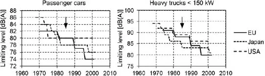
Various authorities aim to reduce the noise level in the environment by issuing requirements for the maximum noise level of critical noise resources. In transport, it is primarily motor vehicles which are subject to noise emission regulations. However, the strict limits cannot be introduced all at once, therefore the reduction is expected to be made gradually over at least 25 years. Newly manufactured vehicles which do not meet specified noise limits do not obtain permission to operate on public roads. Motor vehicle manufacturers have been given sufficient time to implement noise reduction innovations. The time line for noise limits for cars and trucks with an engine power of 150 kW and more is shown in Figure 1.1. Data was taken from the final report of the working party on noise emissions of road vehicles. The arrow pointing at 1985 indicates that in the EU there was a change in measuring procedure. For trucks, this corresponded to 2–4 dB of stricter requirements on top of the other changes; but for cars it corresponded to approximately 2 dB of less stringent requirements.
There is an international standard for the measurement of noise emitted into the environment. Details will be discussed in the last chapter of the book. For now, it is sufficient to note that under certain conditions the Sound Level Metre measures the maximum of the sound pressure level at the point which is at a distance of 7.5 m from the centreline of the track of the vehicle and 1.5 m above the road surface. The same sound pressure level is measured in the USA at the distance which is twice as far away, so limits for this country were raised to about 6 dB in the graph in Figure 1.1. This measurement relates to pass-by noise. The noise level in the vehicle cabin is a separate factor.
So began a race against time for manufacturers of heavy trucks. The sound pressure limit of 84 dB was not difficult to meet. But to produce a heavy-duty vehicle of 80 dB required changing the design. Transmissions can be put into an enclosure with a small reduction of 4 dB in the level of radiated noise or it is possible through a fundamental change in the parameters of gears [2, 3]. This book describes the difficult development which led to a substantial reduction in noise transmission by improving the design of gears. The theme of the book does not address the design, but describes the methods of measurement and signal processing which helped to determine the effect of design modifications or just to verify the correctness of the decision.
1.1 Description of the TATRA Truck Powertrain System
The theory of signal processing is illustrated by examples of the measurement of noise and vibration of the gearbox of the TATRA trucks. It is therefore appropriate to describe the transmission of these vehicles in detail. The truck powertrain system consists of the engine, gearbox, differentials and axles. All these units contain gears. Due to the high rotational speed and transferred torque, gears in a gearbox and axles play a key role in emitting noise. All gears in the TATRA gearbox are of the helical type and the gears in the axles are of the spiral bevel type. The problem of axle noise is serious, but this book does not propose to cover this area of research in detail. In Chapter 7 a method that enables the contribution of the noise level emitted by the axle to the overall noise level of the vehicle to be evaluated is discussed.
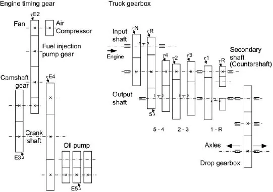
There are a number of gears which rotate in the truck as is shown in Figure 1.2. These include the timing gears of a diesel engine, but these are not a source of serious noise. The main source of noise which is produced by gears is the transmission unit. The older gearbox unit, including a drop or secondary gearbox, is in the left of Figure 1.2.
The secondary gearbox is sometimes called the drop gearbox due to the fact that this gearbox reduces the rotational speed. In the case of the TATRA trucks, the drop gearbox transfers power to the level of the central tube, which is the backbone of the chassis structure. The main gearbox comprises two stages and has five basic gears and reverse. As all the basic gears are split (R, N) the total number of the basic gears is extended to ten forward and two reverse gears. The gears are designated by a combination of the number character (1 up to 5 or 6) and letter (R or N), for example ‘3N’. According to the EEC regulations valid at the beginning of the 1990s, the basic gears selected for the pass-by tests are 3, 4 and 5. The drop gearbox is either the compound gear train with an idler gear or the two-stage gearbox, extending the number of gears to 12. TATRA does not use a planetary gearbox as the drop gearbox.
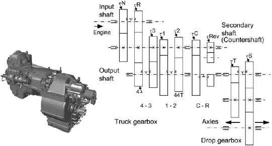
A kinematic scheme of the newest model of the TATRA gearbox is shown in Figure 1.3. The drop gearbox has two gear ratios in contrast to the old model of the gearbox. As is evident from the kinematic schemes both transmissions are manual and all the gears are synchronised.
1.2 Test Stands
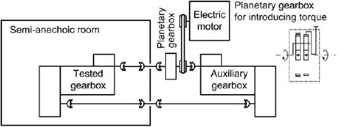
The operating conditions of gearboxes can be simulated using test rigs to drive the gearbox in a similar way to the pass-by noise test. The configuration of the closed loop is energy saving. With the use of an auxiliary planetary gearbox the torque is inserted in the closed circuit while an auxiliary electric motor spins the system at the operational speed. Power, which is the product of angular velocity and torque, then circulates inside the loop. If the auxiliary transmission adapts to different variants of the gearbox under test, then the power consumption of the test rig increases for example, up to 40% of the power that circulates in a closed loop.
An example of a closed circuit arrangement is shown in Figure 1.4. According to current standards for testing the radiated sound pressure level the volume of the chamber should be at least 200 times larger than the volume of the test gearbox. Microphones are placed on the sides of the gearbox in the direction of the truck movement at a distance of 1 m. Accelerometers that are attached on the surface of the gearbox housing near the shaft bearings can provide extensive information about the noise sources. A tacho probe, generating a string of pulses, is usually employed to measure the gearbox-primary-shaft rotational speed. A sensor for measuring the torque is also inserted into the closed loop.
In contrast to the open loop test stand, the back-to-back test rig configuration saves drive energy. The torque to be transmitted by the gearbox is induced by a planetary gearbox. The gearbox under testing is enclosed in a semi-anechoic room with walls and ceiling absorbing sound waves and a reflective floor. The quality of the semi-anechoic room is of great importance for the reliability of the results. The reverberation time should be less than is required in the frequency range from at least 200 to 3 kHz. The input shaft speed is slowly increased from a minimal to maximal RPM while the gearbox is under a load corresponding to full vehicle ‘acceleration’. To simulate the gearbox operational condition during deceleration the noise test continues to slowly decrease from a maximal to minimal RPM.
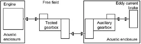
The configuration for measuring an open loop is shown in Figure 1.5. Noise is measured in the open field with two microphones that are located in an anechoic chamber. Because the eddy current brake is used, it is necessary to use an auxiliary gearbox to increase the speed at which this type of the brake is able to effectively load the gearbox by a torque.
References
[1] Sandberg, U. (2001) Noise emissions of road vehicles effect of regulations, Final Report 01-1. I-INCE working party on noise emissions of road vehicles (WP-NERV), International Institute of Noise Control Engineering.
[2] Arenas, J.P. and Crocker, M.J. (2010) Recent trends in porous sound-absorbing materials. Sound and Vibration, 44(7), 12–17.
[3] Zhou, R. and Crocker, M.J. (2010) Sound transmission loss of foam-filled honeycomb sandwich panels using statistical energy analysis and theoretical and measured dynamic properties. Journal of Sound and Vibration, 329(6), 673–686.
![]()
2
Tools for Gearbox Noise and Vibration Frequency Analysis
The signal x(t) is a real or complex function of continuous time t. The other definition points to the fact that the signal contains information which transmits from the source to the receiver. But one of the signal types called a white noise does not formally contain any information. White noise is a totally random signal and the present samples do not depend on the past samples in any way. Signals describe the noise and vibration as time processes, and have common characteristi...