![]()
Chapter I
Functional Principle of Radio Receivers
I.1 Some History to Start
Around 1888 the physicist Heinrich Hertz experimentally verified the existence of electromagnetic waves and Maxwell's theory. At the time his transmitting system consisted of a spark oscillator serving as a high frequency generator to feed a dipole of metal plates. Hertz could recognize the energy emitted by the dipole in the form of sparks across a short spark gap connected to a circular receiving resonator that was located at some distance. However, this rather simple receiver system could not be used commercially.
I.1.1 Resonance Receivers, Fritters, Coherers, and Square-Law Detectors (Detector Receivers)
The road to commercial applications opened only after the Frenchman Branly was able to detect the received high-frequency signal by means of a coherer, also known as a fritter. His coherer consisted of a tube filled with iron filings and connected to two electrodes. The transfer resistance of this setup decreased with incoming high-frequency pulses, producing a crackling sound in the earphones. When this occurred the iron filings were rearranged in a low-resistance pattern and thus insensitive to further stimulation. To keep them active and maintain high resistance they needed to be subjected to a shaking movement. This mechanical shaking could be produced by a device called a Wagner hammer or knocker. A receiving system comprising of a dipole antenna, a coherer as a detector, a Wagner hammer with direct voltage source and a telephone handset formed the basis for Marconi to make radio technology successful world-wide in the 1890s.
The components of this receiver system had to be modified to meet the demands of wider transmission ranges and higher reliability. An increase in the range was achieved by replacing the simple resonator or dipole by the Marconi antenna. This featured a high vertical radiator as an isolated structure or an expanded fan- or basket-shaped antenna of individual wires with a ground connection. The connection to ground as a ‘return conductor’ had already been used in times of wire-based telegraphy.
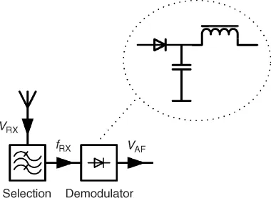
The selectivity which, until then, was determined by the resonant length of the antenna, was optimized by oscillating circuits tuned by means of either variable coils or variable capacitors. At the beginning of the last century a discovery was made regarding the rectifying effect that occurs when scanning the surface of certain elements with a metal pin. This kind of detector often used a galena crystal and eventually replaced the coherer. For a long while it became an inherent part of the detector receiver used by our great-grandparents (Fig. I.1).
The rapid growth of wireless data transmission resulted in further development of receiving systems. Especially, the increase in number and in density of transmitting stations demanded efficient discriminatory power. This resulted in more sophisticated designs which determined the selectivity not only by low-attenuation matching of the circuitry to the antenna but also by including multi-circuit bandpass filters in the circuits which select the frequency. High circuit quality was achieved by the use of silk-braided wires wound on honeycomb-shaped bodies of suitable size or of rotary capacitors of suitable shape and adequate dielectric strength. This increased not only the selectivity but also the accuracy in frequency tuning for station selection.
I.1.2 Development of the Audion
Particularly in military use and in air and sea traffic, wireless telegraphy spread rapidly. With the invention of the electron tube and its first applications as a rectifier and RF amplifier came the discovery, in 1913, of the feedback principle, another milestone in the development of receiver technology. The use of a triode or multi-grid tube, known as the audion, allowed circuit designs that met all major demands for receiver characteristics. For the first time it was possible to amplify the high-frequency voltage picked up by the antenna several hundred times and to rectify the RF signal simultaneously. The unique feature, however, was the additional use of the feedback principle, which allowed part of the amplified high frequency signal from the anode to be returned in the proper phase to the grid of the same tube. The feedback was made variable and, when adjusted correctly, resulted in a pronounced undamping of the frequency-determining grid circuit. This brought a substantial reduction of the receive bandwidth (Section III.6.1) and with it a considerable improvement of the selectivity. Increasing the feedback until the onset of oscillation offered the possibility of making the keyed RF voltage audible as a beat note. In 1926, when there were approximately one million receivers Germany, the majority of designs featured the audion principle, while others used simple detector circuits.
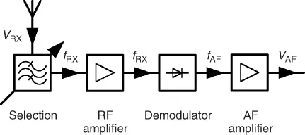
The nomenclature for audion circuits used ‘v’, derived from the term ‘valve’ for an electron tube. Thus, for example, 0-v-0 designates a receiver without RF amplifier and without AF amplifier; 1-v-2 is an audion with one RF amplifier and two AF amplifier stages. Improvements in the selective power and in frequency tuning as well as the introduction of direct-voltage supply or AC power adapters resulted in a vast number of circuit variations for industrially produced receiver models. The general interest in this new technology grew continuously and so did the number of amateur radio enthusiasts who built their devices themselves. All these various receivers had one characteristic in common: They always amplified, selected and demodulated the desired signal at the same frequency. For this reason they were called tuned radio frequency (TRF) receivers (Fig. I.2).
Due to its simplicity the TRF receiver enabled commercial production at a low price, which resulted in the wide distribution of radio broadcasting as a new medium (probably the best-known German implementation was the ‘Volksempfänger’ (public radio receiver)). Even self-built receivers were made simple, since the required components were readily available at low cost. However, the tuned radio frequency receiver had inherent technical deficiencies. High input voltages cause distortions with the audion, and circuits with several cascading RF stages of high amplification tend to self-excitation. For reasons of electrical synchronization, multiple-circuit tuning is very demanding with respect to mechanical precision and tuning accuracy, and the selectivity achievable with these circuits depends on the frequency (Fig. I.3). Especially the selectivity issue gave rise to the principle of superheterodyne receivers (superhet in short) from 1920 in the US and 10 years later in Europe. The superhet receiver solved the problem in the following way. The received signal was preselected, amplified and fed to a mixer, where it was combined with a variable, internally generated oscillator signal (the heterodyne signal). This signal originating from the local oscillator is also known as the LO injection signal. Mixing the two signals (Section V.4.1) produces (by subtraction) the so-called IF signal (intermediate frequency signal). It is a defined constant RF frequency which, at least in the beginning, for practical and RF-technological reasons was distinctly lower than the receiving frequency. By using this low frequency it was possible not only to amplify the converted signal nearly without self-excitation, but also to achieve a narrow bandwidth by using several high quality bandpass filters. After sufficient amplification the intermediate frequency (IF) signal was demodulated. Because of the advantages of the heterodyne principle the problem of synchronizing the tuning oscillator and RF circuits was willingly accepted. The already vast number of transmitter stations brought about increasing awareness of t...