Radio Receiver Technology
eBook - ePub

Radio Receiver Technology

Principles, Architectures and Applications

Ralf Rudersdorfer

Partager le livre
  1. English
  2. ePUB (adapté aux mobiles)
  3. Disponible sur iOS et Android
eBook - ePub

Radio Receiver Technology

Principles, Architectures and Applications

Ralf Rudersdorfer

DĂ©tails du livre
Aperçu du livre
Table des matiĂšres
Citations

À propos de ce livre

Written by an expert in the field, this book covers the principles, architectures, applications, specifications and characterizations of radio receivers

In this book, the author introduces the reader to the basic principles and theories of present-day communications receiver technology. The first section of the book presents realization concepts at the system level, taking into consideration the various types of users. Details of the circuitry are described providing the reader with an understanding of fully digitized radio receivers, offering an insight into the state-of-the-art.

The remaining sections address radio receivers, particularly as two-port devices. Furthermore, the author outlines the fields of applications (with sample calculations and with reference to practical work) and their features and considers also the specialty of high-quality radio receivers. As can be seen from the multitude of terrestrial applications described in Part II, they are typically used for radio surveillance, signal intelligence, modern radio bearing and at the classical radio services. Parts III and IV describe the entire range of parameters that are useful for the characterization of these receivers. The description starts from the physical effect, or the explanation of the individual parameter, and then proceeds to the measuring technique for determining the parameters, highlighting problems, followed by explanatory notes with applicatory relevance. The measuring procedures described are the result of experiences gained in extended laboratory work and practical testing. With the model shown in Part IV, used for the operational evaluation detailing the intrinsic small range of interpretation, the book covers untreated research in the field. The Appendix provides among others valuable information about the dimensioning of receiving systems and the mathematical derivation of non-linear effects and as well as a useful method for converting different level specifications.

Key Features:

  • Introduces the basic principles and theories of present-day technology
  • Discusses concepts at system level (aligned to the various types of users)
  • Addresses (fully) digitized radio receivers focusing on the state-of-the-art
  • Close contacts to the industry were utilized to show background information
  • Enables the reader to comprehend and evaluate the characteristic features and the performance of such systems
  • Examines the entire range of parameters that are characteristic of the technology including the physical effect and measuring techniques
  • Includes results of experiences gained in extended laboratory work and practical testing with examples
  • Provides a uniform and systematic approach for ease of understanding e.g. many didactic figures for the visual illustration have been newly created as well as complete real-world examples

This book will be an excellent resource to understand the principles of work, for professionals developing and testing radio receivers, for receiver users (e.g. at regulatory agencies, surveillance centers, secret services, classical radio communications services), technicians, engineers and technicians who work with RF-measurement instruments, postgraduate students studying in the field and university lecturers. Chartered radio amateurs and handlers/operators will also find this book insightful. Due to high level of detail, it also serves as a reference. By using the carefully edited alphabetical index with over 1, 200 entries, the appropriate explanations can be found quickly in the text.

Foire aux questions

Comment puis-je résilier mon abonnement ?
Il vous suffit de vous rendre dans la section compte dans paramĂštres et de cliquer sur « RĂ©silier l’abonnement ». C’est aussi simple que cela ! Une fois que vous aurez rĂ©siliĂ© votre abonnement, il restera actif pour le reste de la pĂ©riode pour laquelle vous avez payĂ©. DĂ©couvrez-en plus ici.
Puis-je / comment puis-je télécharger des livres ?
Pour le moment, tous nos livres en format ePub adaptĂ©s aux mobiles peuvent ĂȘtre tĂ©lĂ©chargĂ©s via l’application. La plupart de nos PDF sont Ă©galement disponibles en tĂ©lĂ©chargement et les autres seront tĂ©lĂ©chargeables trĂšs prochainement. DĂ©couvrez-en plus ici.
Quelle est la différence entre les formules tarifaires ?
Les deux abonnements vous donnent un accĂšs complet Ă  la bibliothĂšque et Ă  toutes les fonctionnalitĂ©s de Perlego. Les seules diffĂ©rences sont les tarifs ainsi que la pĂ©riode d’abonnement : avec l’abonnement annuel, vous Ă©conomiserez environ 30 % par rapport Ă  12 mois d’abonnement mensuel.
Qu’est-ce que Perlego ?
Nous sommes un service d’abonnement Ă  des ouvrages universitaires en ligne, oĂč vous pouvez accĂ©der Ă  toute une bibliothĂšque pour un prix infĂ©rieur Ă  celui d’un seul livre par mois. Avec plus d’un million de livres sur plus de 1 000 sujets, nous avons ce qu’il vous faut ! DĂ©couvrez-en plus ici.
Prenez-vous en charge la synthÚse vocale ?
Recherchez le symbole Écouter sur votre prochain livre pour voir si vous pouvez l’écouter. L’outil Écouter lit le texte Ă  haute voix pour vous, en surlignant le passage qui est en cours de lecture. Vous pouvez le mettre sur pause, l’accĂ©lĂ©rer ou le ralentir. DĂ©couvrez-en plus ici.
Est-ce que Radio Receiver Technology est un PDF/ePUB en ligne ?
Oui, vous pouvez accĂ©der Ă  Radio Receiver Technology par Ralf Rudersdorfer en format PDF et/ou ePUB ainsi qu’à d’autres livres populaires dans Technology & Engineering et Mobile & Wireless Communications. Nous disposons de plus d’un million d’ouvrages Ă  dĂ©couvrir dans notre catalogue.

Informations

Éditeur
Wiley
Année
2013
ISBN
9781118647844

Chapter I

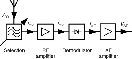
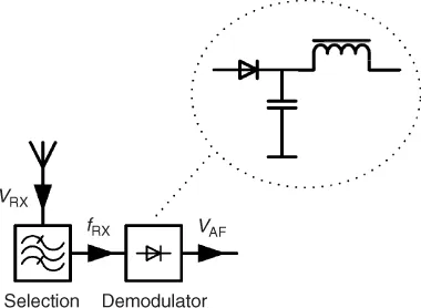
Functional Principle of Radio Receivers

I.1 Some History to Start

Around 1888 the physicist Heinrich Hertz experimentally verified the existence of electromagnetic waves and Maxwell's theory. At the time his transmitting system consisted of a spark oscillator serving as a high frequency generator to feed a dipole of metal plates. Hertz could recognize the energy emitted by the dipole in the form of sparks across a short spark gap connected to a circular receiving resonator that was located at some distance. However, this rather simple receiver system could not be used commercially.

I.1.1 Resonance Receivers, Fritters, Coherers, and Square-Law Detectors (Detector Receivers)

The road to commercial applications opened only after the Frenchman Branly was able to detect the received high-frequency signal by means of a coherer, also known as a fritter. His coherer consisted of a tube filled with iron filings and connected to two electrodes. The transfer resistance of this setup decreased with incoming high-frequency pulses, producing a crackling sound in the earphones. When this occurred the iron filings were rearranged in a low-resistance pattern and thus insensitive to further stimulation. To keep them active and maintain high resistance they needed to be subjected to a shaking movement. This mechanical shaking could be produced by a device called a Wagner hammer or knocker. A receiving system comprising of a dipole antenna, a coherer as a detector, a Wagner hammer with direct voltage source and a telephone handset formed the basis for Marconi to make radio technology successful world-wide in the 1890s.
The components of this receiver system had to be modified to meet the demands of wider transmission ranges and higher reliability. An increase in the range was achieved by replacing the simple resonator or dipole by the Marconi antenna. This featured a high vertical radiator as an isolated structure or an expanded fan- or basket-shaped antenna of individual wires with a ground connection. The connection to ground as a ‘return conductor’ had already been used in times of wire-based telegraphy.
The selectivity which, until then, was determined by the resonant length of the antenna, was optimized by oscillating circuits tuned by means of either variable coils or variable capacitors. At the beginning of the last century a discovery was made regarding the rectifying effect that occurs when scanning the surface of certain elements with a metal pin. This kind of detector often used a galena crystal and eventually replaced the coherer. For a long while it became an inherent part of the detector receiver used by our great-grandparents (Fig. I.1).
Figure I.1 Functional blocks of the detector receiver. The demodulator circuit shown separately represents the actual detector. With the usually weak signals received the kink in the characteristic curve of the demodulator diode is not very pronounced compared to the signal amplitude. The detector therefore has a nonlinear characteristic. It is also known as a square-law detector. (The choke blocks the remaining RF voltage. In the simplest versions it is omitted entirely.)
c01f001
The rapid growth of wireless data transmission resulted in further development of receiving systems. Especially, the increase in number and in density of transmitting stations demanded efficient discriminatory power. This resulted in more sophisticated designs which determined the selectivity not only by low-attenuation matching of the circuitry to the antenna but also by including multi-circuit bandpass filters in the circuits which select the frequency. High circuit quality was achieved by the use of silk-braided wires wound on honeycomb-shaped bodies of suitable size or of rotary capacitors of suitable shape and adequate dielectric strength. This increased not only the selectivity but also the accuracy in frequency tuning for station selection.

I.1.2 Development of the Audion

Particularly in military use and in air and sea traffic, wireless telegraphy spread rapidly. With the invention of the electron tube and its first applications as a rectifier and RF amplifier came the discovery, in 1913, of the feedback principle, another milestone in the development of receiver technology. The use of a triode or multi-grid tube, known as the audion, allowed circuit designs that met all major demands for receiver characteristics. For the first time it was possible to amplify the high-frequency voltage picked up by the antenna several hundred times and to rectify the RF signal simultaneously. The unique feature, however, was the additional use of the feedback principle, which allowed part of the amplified high frequency signal from the anode to be returned in the proper phase to the grid of the same tube. The feedback was made variable and, when adjusted correctly, resulted in a pronounced undamping of the frequency-determining grid circuit. This brought a substantial reduction of the receive bandwidth (Section III.6.1) and with it a considerable improvement of the selectivity. Increasing the feedback until the onset of oscillation offered the possibility of making the keyed RF voltage audible as a beat note. In 1926, when there were approximately one million receivers Germany, the majority of designs featured the audion principle, while others used simple detector circuits.
The nomenclature for audion circuits used ‘v’, derived from the term ‘valve’ for an electron tube. Thus, for example, 0-v-0 designates a receiver without RF amplifier and without AF amplifier; 1-v-2 is an audion with one RF amplifier and two AF amplifier stages. Improvements in the selective power and in frequency tuning as well as the introduction of direct-voltage supply or AC power adapters resulted in a vast number of circuit variations for industrially produced receiver models. The general interest in this new technology grew continuously and so did the number of amateur radio enthusiasts who built their devices themselves. All these various receivers had one characteristic in common: They always amplified, selected and demodulated the desired signal at the same frequency. For this reason they were called tuned radio frequency (TRF) receivers (Fig. I.2).
Figure I.2 Design of the tuned radio frequency receiver. Preamplification of the RF signal received has resulted in a linearization of the demodulation process. The amplified signal appears to be rather strong compared to the voltage threshold of the demodulator diode (compare with Figure I.1).
c01f002
Due to its simplicity the TRF receiver enabled commercial production at a low price, which resulted in the wide distribution of radio broadcasting as a new medium (probably the best-known German implementation was the ‘VolksempfĂ€nger’ (public radio receiver)). Even self-built receivers were made simple, since the required components were readily available at low cost. However, the tuned radio frequency receiver had inherent technical deficiencies. High input voltages cause distortions with the audion, and circuits with several cascading RF stages of high amplification tend to self-excitation. For reasons of electrical synchronization, multiple-circuit tuning is very demanding with respect to mechanical precision and tuning accuracy, and the selectivity achievable with these circuits depends on the frequency (Fig. I.3). Especially the selectivity issue gave rise to the principle of superheterodyne receivers (superhet in short) from 1920 in the US and 10 years later in Europe. The superhet receiver solved the problem in the following way. The received signal was preselected, amplified and fed to a mixer, where it was combined with a variable, internally generated oscillator signal (the heterodyne signal). This signal originating from the local oscillator is also known as the LO injection signal. Mixing the two signals (Section V.4.1) produces (by subtraction) the so-called IF signal (intermediate frequency signal). It is a defined constant RF frequency which, at least in the beginning, for practical and RF-technological reasons was distinctly lower than the receiving frequency. By using this low frequency it was possible not only to amplify the converted signal nearly without self-excitation, but also to achieve a narrow bandwidth by using several high quality bandpass filters. After sufficient amplification the intermediate frequency (IF) signal was demodulated. Because of the advantages of the heterodyne principle the problem of synchronizing the tuning oscillator and RF circuits was willingly accepted. The already vast number of transmitter stations brought about increasing awareness of t...

Table des matiĂšres