![]()
CHAPTER 1
EQUILIBRIUM OF FORCES
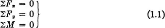
1.1. Equations of Equilibrium. One of the first steps in the design of a machine or structure is the determination of the loads acting on each member. The loads acting on an airplane may occur in various landing or flight conditions. The loads may be produced by ground reactions on the wheels, by aerodynamic forces on the wings and other surfaces, or by forces exerted on the propeller. The loads are resisted by the weight or inertia of the various parts of the airplane. Several loading conditions must be considered, and each member must be designed for the combination of conditions which produces the highest stress in the member. For practically all members of the airplane structure the maximum loads occur when the airplane is in an accelerated flight or landing condition and the external loads are not in equilibrium. If, however, the inertia loads are also considered, they will form a system of forces which are in equilibrium with the external loads. In the design of any member it is necessary to find all the forces acting on the member, including inertia forces. Where these forces are in the same plane, as is often the case, the following equations of static equilibrium apply to any isolated portion of the structure:
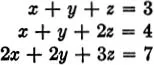
The terms ΣFx and ΣFy represent the summations of the components of forces along x and y axes, which may be taken in any two arbitrary directions. The term ΣM represents the sum of the moments of all forces about any arbitrarily chosen point in the plane. Each of these equations may be set up in an infinite number of ways for any problem, since the directions of the axes and the center of moments may be chosen arbitrarily. Only three independent equations exist for any free body, however, and only three unknown forces may be found from the equations. If, for example, an attempt is made to find four unknown forces by using the two force equations and moment equations about two points, the four equations cannot be solved because they are not independent, i.e., one of the equations can be derived from the other three. The following equations cannot be solved for the numerical values of the three unknowns because they are not independent.
The third equation may be obtained by adding the first two equations, and consequently does not represent an independent condition.
In the analysis of a structure containing several members it is necessary to draw a free-body diagram for each member, showing all the forces acting on that member. It is not possible to show these forces on a composite sketch of the entire structure, since equal and opposite forces act at all joints and an attempt to designate the correct direction of the force on each member will be confusing. In applying the equations of statics it is desirable to choose the axes and centers of moments so that only one unknown appears in each equation.
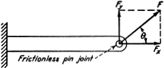
Many structural joints are made with a single bolt or pin. Such joints are assumed to have no resistance to rotation. The force at such a joint must pass through the center of the pin, as shown in
Fig. 1.1, since the moment about the center of the pin must be zero. The force at the pin joint has two unknown quantities, the magnitude
F and the direction
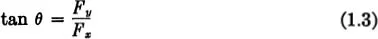
. It is usually more convenient to find the two unknown components,
Fx and
Fy, from which
F and
can be found by the equations:
The statics problem is considered as solved when the components Fx and Fy at each joint are obtained.
FIG. 1.1.
FIG. 1.2.
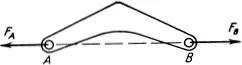
1.2. Two-force Members. When a structural member has forces acting at only two points, these forces must be equal and opposite, as shown in Fig. 1.2. Since moments about point A must be zero, the force FB must pass through point A. Similarly the force FA must pass through point B for moments about point B to be zero. From a summation of forces, the forces FB and FA must have equal magnitudes but opposite directions. Two-force members are frequently used in aircraft and other structures, since simple tension or compression members are usually the lightest members for transmitting forces. Where possible, two-force members are straight, rather than curved as shown in Fig. 1.2. Structures made up entirely of two-force members are called trusses and are frequently used in fuselages, engine mounts, and other aircraft structures, as well as in bridge and building structure...