- 336 pages
- English
- ePUB (mobile friendly)
- Available on iOS & Android
eBook - ePub
Analog Circuits Cookbook
About this book
Analog Circuits Cookbook is a collection of tried and tested recipes form the masterchef of analog and RF design. Based on articles from Electronics World, this book provides a diet of high quality design techniques and applications, and proven ciruit designs, all concerned with the analog, RF and interface fields of electronics. Ian Hickman uses illustrations and examples rather than tough mathematical theory to present a wealth of ideas and tips based on his own workbench experience.
This second edition includes 10 of Hickman's latest articles, alongside 20 of his most popular classics. The new material includes articles on power supplies, filters using negative resistance, phase noise and video surveillance systems.
- Essential reading for all circuit design professionals and advanced hobbyists
- Contains 10 of Ian Hickman's latest articles, alongside 20 of his most popular classics
Trusted by 375,005 students
Access to over 1.5 million titles for a fair monthly price.
Study more efficiently using our study tools.
Information
1
Advanced circuit techniques, components and concepts
Negative approach to positive thinking
There is often felt to be something odd about negative components, such as negative resistance or inductance, an arcane aura setting them apart from the real world of practical circuit design. The circuit designer in the development labs of a large firm can go along to stores and draw a dozen 100 kΩ resistors or half a dozen 10 μF tantalums for example, but however handy it would be, it is not possible to go and draw a −4.7 kΩ resistor. Yet negative resistors would be so useful in a number of applications; for example when using mismatch pads to bridge the interfaces between two systems with different characteristic impedances. Even when the difference is not very great, for example testing a 75 Ω bandpass filter using a 50 Ω network analyser, the loss associated with each pad is round 6 dB, immediately cutting 12 dB off how far down you can measure in the stopband. With a few negative resistors in the junk box, you could make a pair of mismatch pads with 0 dB insertion loss each.
But in circuit design, negative component values do turn up from time to time and the experienced designer knows when to accommodate them, and when to redesign in order to avoid them. For example, in a filter design it may turn out that a −3 pF capacitor, say, must be added between nodes X and Y. Provided that an earlier stage of the computation has resulted in a capacitance of more than this value appearing between those nodes, there is no problem; it is simply reduced by 3 pF to give the Final value. In the case where the final value is still negative, it may be necessary to redesign to avoid the problem, particularly at UHF and above. At lower frequencies, there is always the option of using a ‘real’ negative capacitator (or something that behaves exactly like one); this is easily implemented with an ‘ordinary’ (positive) capacitor and an opamp or two, as are negative resistors and inductors. However, before looking at negative components using active devices, note that they can be implemented in entirely passive circuits if you know how (Roddam, 1959). Figure 1.1(a) shows a parallel tuned circuit placed in series with a signal path, to act as a trap, notch or rejector circuit. Clearly it only works well if the load resistance Rl is low compared with the tuned circuit’s dynamic impedance Rd. If Rl is near infinite, the trap makes no difference, so Rd should be much greater than Rl; indeed, ideally we would make Rd infinite by using an inductor (and capacitor) with infinite Q. An equally effective ploy would be to connect a resistance of −Rd in parallel with the capacitor, cancelling out the coil’s loss exactly and effectively raising Q to infinity. This is quite easily done, as in Figure 1.1(b), where the capacitor has been split in two, and the tuned circuit’s dynamic resistance Rd (Rd = QωL, assuming the capacitor is perfect) replaced by an equivalent series loss component r associated with the coil (r = ωL/Q). From the junction of the two capacitors, a resistor R has been connected to ground. This forms a star network with the two capacitors, and the next step is to transform it to a delta network, using the star-delta equivalence formulae. The result is as in Figure 1.1(c) and the circuit can now provide a deep notch even Rl is infinite, owing to the presence of the shunt impedance Zp across the output, if the right value for R is chosen. So, let R′ = –r, making the resistive component of Zs (in parallel form) equal to –Rd. Now R′ turns out to be −1/(4ω2C2R) and equating this to –r gives R = Rd/4.
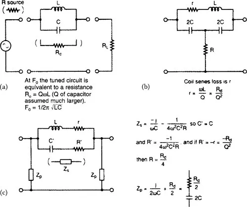
Figure 1.1 (a) A parallel tuned circuit used as a rejector. The notch depth is set by the ratio of the tuned circuit’s dynamic resistance Rdand the load resistance RI. At F0 the tuned circuit is equivalent to a resistance Rd = QωL (Q of capacitor assumed much larger). F0 = 1/2π√(LC). (b) The circuit modified to provide a deep notch, tuned frequency unchanged. Coil series losses r = ωL/Q = Rd/Q2(c) As (b) but with the star network transformed to the equivalent delta network. Zs = (–j/ωC) −1/(4ω2C2R). So C′ = C and R′ = −1/(4ω2C2R) and if R′ = −r = −Rd/Q2then R = Rd/4, Zp = (j/2ωC) + (Rd/2)
Negative inductor
Now for a negative inductor, and all entirely passive – not an opamp in sight. Figure 1.2(a) shows a section of constant-K lowpass filter acting as a lumped passive delay line. It provides a group delay dB/dω of √(LC) seconds per section. Figure 1.2(b) at dc and low frequencies, maintained fairly constant over much of the passband of the filter. A constant group delay (also known as envelope delay) means that all frequency components passing through the delay line (or through a filter of any sort) emerge at the same time as each other at the far end, implying that the phase delay B = ω √(LC) radians per section is proportional to frequency. (Thus a complex waveform such as an AM signal with 100% modulation will emerge unscathed, with its envelope delayed but otherwise preserved unchanged. Similarly, a squarewave will be undistorted provided all the significant harmonics lie within the range of frequencies for which a filter exhibits a constant group delay. Constant group delay is thus particularly important for an IF bandpass filter handling phase modulated signals.) If you connect an inductance L′ (of suitable value) in series with each of the shunt capacitors, the line becomes an ‘m-derived’ lowpass filter instead of a constant-K filter, with the result that the increase of attenuation beyond the cut-off frequency is much more rapid. However, that is no great benefit in this application, a delay line is desired above all to provide a constant group delay over a given bandwidth and the variation in group delay of an m-derived filter is much worse even than that of a constant-K type. Note that L′ may not be a separate physical component at all, but due to mutual coupling between adjacent sections of series inductance, often wound one after the other, between tapping points on a cylindrical former in one long continuous winding. If the presence of shunt inductive components L′ makes matters worse than the constant-K case, the addition of negative L′ improves matters. This is easily arranged (Figure 1.2(c)) by winding each series section of inductance in the opposite sense to the previous one.
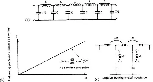
Figure 1.2 (a) Basic delay line – (b) providing a delay of √(LC) seconds per section at dc and low frequencies. (c) Connection of negative inductance in the shunt arms to linearise the group delay over a larger proportion of the filter’s passband. Not a physical component, it is implemented by negative mutual inductance (bucking coupling) between sections of series inductance
Real pictures
Now for some negative components that may, in a sense, seem more real, implemented using active circuitry. Imagine connecting the output of an adjustable power supply to a 1 Ω resistor whose other end, like that of the supply’s return lead, is connected to ground. Then for every volt positive (or negative) that you apply to the resistor, 1 A will flow into (or out of) it. Now imagine that, without changing the supply’s connections, you arrange that the previously earthy end of the resistor is automatically ja...
Table of contents
- Cover image
- Title page
- Table of Contents
- Copyright page
- Preface to second edition
- 1: Advanced circuit techniques, components and concepts
- 2: Audio
- 3: Measurements (audio and video)
- 4: Measurements (rf)
- 5: Opto
- 6: Power supplies and devices
- 7: RF circuits and techniques
- Index
Frequently asked questions
Yes, you can cancel anytime from the Subscription tab in your account settings on the Perlego website. Your subscription will stay active until the end of your current billing period. Learn how to cancel your subscription
No, books cannot be downloaded as external files, such as PDFs, for use outside of Perlego. However, you can download books within the Perlego app for offline reading on mobile or tablet. Learn how to download books offline
Perlego offers two plans: Essential and Complete
- Essential is ideal for learners and professionals who enjoy exploring a wide range of subjects. Access the Essential Library with 800,000+ trusted titles and best-sellers across business, personal growth, and the humanities. Includes unlimited reading time and Standard Read Aloud voice.
- Complete: Perfect for advanced learners and researchers needing full, unrestricted access. Unlock 1.5M+ books across hundreds of subjects, including academic and specialized titles. The Complete Plan also includes advanced features like Premium Read Aloud and Research Assistant.
We are an online textbook subscription service, where you can get access to an entire online library for less than the price of a single book per month. With over 1.5 million books across 990+ topics, we’ve got you covered! Learn about our mission
Look out for the read-aloud symbol on your next book to see if you can listen to it. The read-aloud tool reads text aloud for you, highlighting the text as it is being read. You can pause it, speed it up and slow it down. Learn more about Read Aloud
Yes! You can use the Perlego app on both iOS and Android devices to read anytime, anywhere — even offline. Perfect for commutes or when you’re on the go.
Please note we cannot support devices running on iOS 13 and Android 7 or earlier. Learn more about using the app
Please note we cannot support devices running on iOS 13 and Android 7 or earlier. Learn more about using the app
Yes, you can access Analog Circuits Cookbook by Ian Hickman in PDF and/or ePUB format, as well as other popular books in Technology & Engineering & Industrial Design. We have over 1.5 million books available in our catalogue for you to explore.