
eBook - ePub
Form and Forces
Designing Efficient, Expressive Structures
Edward Allen, Waclaw Zalewski
This is a test
Buch teilen
- English
- ePUB (handyfreundlich)
- Über iOS und Android verfügbar
eBook - ePub
Form and Forces
Designing Efficient, Expressive Structures
Edward Allen, Waclaw Zalewski
Angaben zum Buch
Buchvorschau
Inhaltsverzeichnis
Quellenangaben
Über dieses Buch
Here, in one volume, is all the architect needs to know to participate in the entire process of designing structures. Emphasizing bestselling author Edward Allen's graphical approach, the book enables you to quickly determine the desired form of a building or other structure and easily design it without the need for complex mathematics. This unique text teaches the whole process of structural design for architects, including selection of suitable materials, finding a suitable configuration, finding forces and size members, designing appropriate connections, and proposing a feasible method of erection. Chapters are centered on the design of a whole structure, from conception through construction planning.
Häufig gestellte Fragen
Wie kann ich mein Abo kündigen?
Gehe einfach zum Kontobereich in den Einstellungen und klicke auf „Abo kündigen“ – ganz einfach. Nachdem du gekündigt hast, bleibt deine Mitgliedschaft für den verbleibenden Abozeitraum, den du bereits bezahlt hast, aktiv. Mehr Informationen hier.
(Wie) Kann ich Bücher herunterladen?
Derzeit stehen all unsere auf Mobilgeräte reagierenden ePub-Bücher zum Download über die App zur Verfügung. Die meisten unserer PDFs stehen ebenfalls zum Download bereit; wir arbeiten daran, auch die übrigen PDFs zum Download anzubieten, bei denen dies aktuell noch nicht möglich ist. Weitere Informationen hier.
Welcher Unterschied besteht bei den Preisen zwischen den Aboplänen?
Mit beiden Aboplänen erhältst du vollen Zugang zur Bibliothek und allen Funktionen von Perlego. Die einzigen Unterschiede bestehen im Preis und dem Abozeitraum: Mit dem Jahresabo sparst du auf 12 Monate gerechnet im Vergleich zum Monatsabo rund 30 %.
Was ist Perlego?
Wir sind ein Online-Abodienst für Lehrbücher, bei dem du für weniger als den Preis eines einzelnen Buches pro Monat Zugang zu einer ganzen Online-Bibliothek erhältst. Mit über 1 Million Büchern zu über 1.000 verschiedenen Themen haben wir bestimmt alles, was du brauchst! Weitere Informationen hier.
Unterstützt Perlego Text-zu-Sprache?
Achte auf das Symbol zum Vorlesen in deinem nächsten Buch, um zu sehen, ob du es dir auch anhören kannst. Bei diesem Tool wird dir Text laut vorgelesen, wobei der Text beim Vorlesen auch grafisch hervorgehoben wird. Du kannst das Vorlesen jederzeit anhalten, beschleunigen und verlangsamen. Weitere Informationen hier.
Ist Form and Forces als Online-PDF/ePub verfügbar?
Ja, du hast Zugang zu Form and Forces von Edward Allen, Waclaw Zalewski im PDF- und/oder ePub-Format sowie zu anderen beliebten Büchern aus Architecture & Architecture Design. Aus unserem Katalog stehen dir über 1 Million Bücher zur Verfügung.
Information
Chapter 1
Designing a Series of Suspension Footbridges
- Basic definitions of statics: loads, forces, tension, compression, stress
- Free-body diagrams; vectors and scalars; static equilibrium of concurrent forces
- The force polygon and funicular polygon for funicular structures; Bow's notation
- Detailing steel rod elements in tension, and anchoring to rock
- Lateral stability; stiffening a tensile structure
- Construction detailing and planning
We have been commissioned to design a series of footbridges for a new scenic trail that will wind through a deep, narrow canyon in a national park in the southwestern United States. The walls of the canyon are often vertical and sometimes overhang, so that the trail must move from one side of the canyon to the other at a number of locations to follow a route that will avoid the steepest walls and minimize excavation of the rock. The lengths (spans) of the bridges will vary between 40 and 100 ft. The decks of all the bridges (the walking surfaces) will be 4 ft wide.
Design Concept
We have already developed, in cooperation with the Park Service, a basic design concept and a simple system of components for making these bridges (Figures 1.1, 1.2). Because of the remoteness of the bridge sites and the difficulty of working in the narrow canyon while standing on narrow rock ledges, as much of the work as possible will be done on components in a contractor's workshop. They will then be trucked to the site, where a construction crew will assemble them.
Figure 1.1 This suspension span of 40 ft is the first bridge we will consider in this chapter.
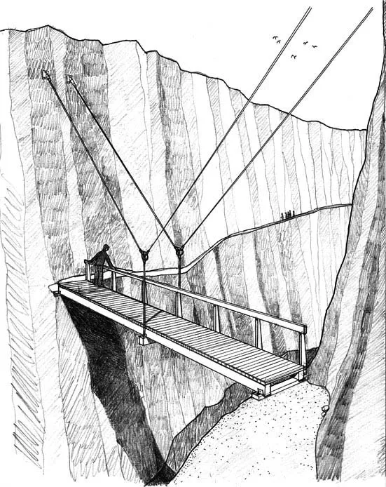
Figure 1.2 An exploded view of the construction system for the suspension bridges in this chapter reveals its component parts.
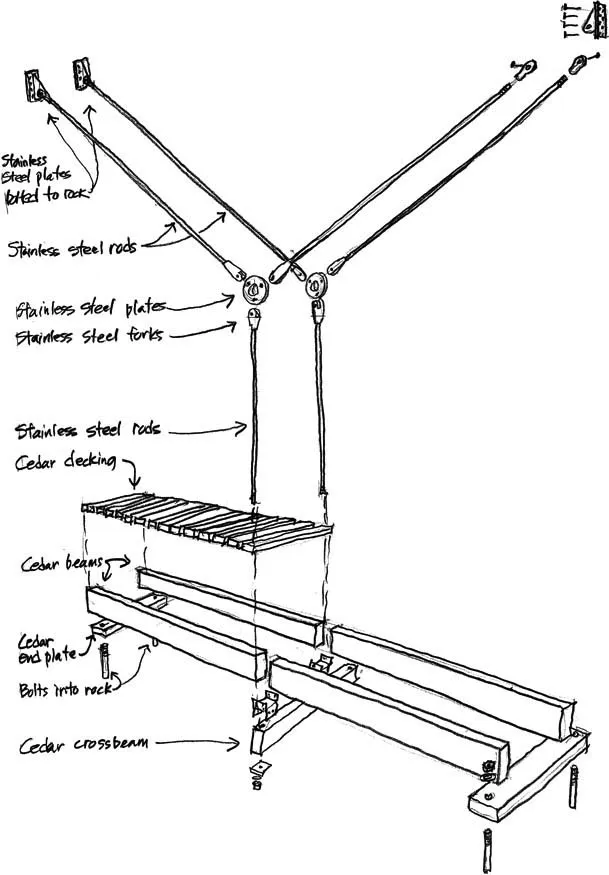
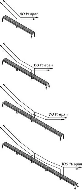
The beams of each bridge are made of wood and will be brought to the site in 20-ft lengths. Shorter lengths can be cut as needed to adjust bridge lengths to particular sites. We will support the ends of the beams that occur over the empty space of the canyon on short wood crossbeams that hang from steel rods. The rods will transmit their forces to steel plates anchored into the rock of the canyon walls. The beams, crossbeams, and rods will be used as a modular system to build suspension bridges of any necessary length for this trail (Figure 1.3). Suspension bridges tend to be lighter in weight than any other kind of bridge, which makes them particularly appropriate for the remote, difficult sites where they must be built in this park.
Figure 1.3 The construction system is modular, enabling it to be used for bridges of various spans.
We have selected rods rather than cables because these bridges are small and the loads to be supported are correspondingly low. Cables, if we were to use them, would be very small in diameter, which would make them vulnerable to vandalism. Because the steel from which the rods are made is not as strong as that used in cables, the rods that we will use will be somewhat larger in diameter than cables of the same capacity. Rods are also easier and less costly to connect than cables. We will learn about cables and their connections in Chapter 2, in the context of a structure with much longer spans, where cables are appropriate and economical.
The beams and deck boards for the bridges are sawn from red cedar logs. We will use them in their rough, unplaned state, in keeping with the rustic nature of the canyon. Furthermore, rough beams are enough larger in dimension than planed ones that they have substantially larger structural capacities. Red cedar contains natural substances that are toxic to decay fungi, making the wood resistant to rot. However, cedar is a very soft, low-density wood that erodes gradually when exposed to severe winter weather, losing a few hundredths of an inch from each surface every year. We have specified larger beams than are structurally necessary in order to provide for a few decades of erosion before they will have to be replaced.
With stainless steel rods and fittings, which do not rust, and cedar beams, which do not decay, the bridges will need no paint or chemical preservatives and should last for decades with little maintenance.
The Challenge
Our challenge is to design the bridges for this trail individually, taking into account for each of them the length of its span and the places above it where the rock is sufficiently solid to support the steel anchor plates. All the bridge sites have been surveyed to provide us with this information. As part of our design work, we need to determine the shapes that the rods will take in each situation, and the forces that they must transmit. This will enable us to specify the required lengths and diameters of the rods.
Construction Details
We have given considerable thought to how the bridges will be put together. Figure 1.4 shows details of the major features. The rods are connected to the rock walls of the canyon with stainless steel anchor plates. Each anchor plate is secured with stainless steel bolts that are inserted into holes drilled in the rock and embedded there with grout, a fine-grained, high-strength mixture of sand, portland cement, and chemical admixtures that increase its strength and limit its shrinkage. The grout is poured into the holes in the form of a paste that hardens to unite the bolts securely with the rock. The rods, anchor plate assemblies, and other metallic components are all custom-fabricated for each bridge. We will determine the diameters of the rods in accordance with the amount of force each must carry when the bridge is fully loaded.
Figure 1.4 Typical details of the suspension bridge construction system.
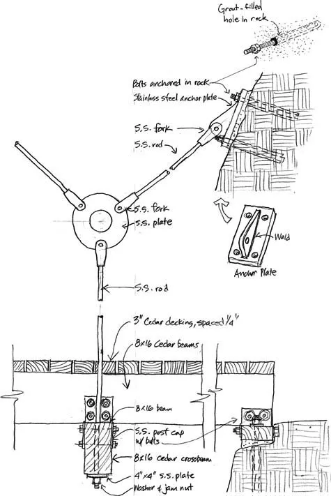
The fabricator of the steel rods will prepare them to the exact lengths needed for each bridge. A jaw fitting (also called a fork or clevis) will be used wherever a rod joins a plate. Where a rod supports a wood beam, it will pass vertically through a hole drilled in the beam and a matching hole in a stainless steel plate 3/8 in. thick on the bottom of the beam (Figure 1.4). A circular washer and stainless steel jam nut transmit the force in the rod securely to the plate. The plate spreads this force over a large enough area of wood that the wood is not crushed. The jam nut is designed to develop a high degree of friction against the threaded rod so that it will not unscrew accidentally. The screw threads and nuts allow for easy assembly and fine-scale adjustment of the vertical positions of the beams, as well as easy disassembly when needed.
Where a vertical rod from a beam meets the sloping rods from the rock anchors, we will attach the rods with forks to a circular steel plate connector, as shown in Figure 1.4. A jaw fitting at the bottom of the plate will transfer force from the vertical rod to the plate, and the plate will pass this same force to the sloping rods and thence to the anc...