Smart Solar PV Inverters with Advanced Grid Support Functionalities
eBook - ePub

Smart Solar PV Inverters with Advanced Grid Support Functionalities

Rajiv K. Varma

Buch teilen
  1. English
  2. ePUB (handyfreundlich)
  3. Über iOS und Android verfügbar
eBook - ePub

Smart Solar PV Inverters with Advanced Grid Support Functionalities

Rajiv K. Varma

Angaben zum Buch
Buchvorschau
Inhaltsverzeichnis
Quellenangaben

Über dieses Buch

Learn the fundamentals of smart photovoltaic (PV) inverter technology with this insightful one-stop resource

Smart Solar PV Inverters with Advanced Grid Support Functionalities presents a comprehensive coverage of smart PV inverter technologies in alleviating grid integration challenges of solar PV systems and for additionally enhancing grid reliability. Accomplished author Rajiv Varma systematically integrates information from the wealth of knowledge on smart inverters available from EPRI, NREL, NERC, SIWG, EU-PVSEC, CIGRE, IEEE publications; and utility experiences worldwide. The book further presents a novel, author-developed and patented smart inverter technology for utilizing solar PV plants both in the night and day as a Flexible AC Transmission System (FACTS) Controller STATCOM, named PV-STATCOM. Replete with case studies, this book includes over 600 references and 280 illustrations.

Smart Solar PV Inverters with Advanced Grid Support Functionalities' features include:

  • Concepts of active and reactive power control; description of different smart inverter functions, and modeling of smart PV inverter systems
  • Distribution system applications of PV-STATCOM for dynamic voltage control, enhancing connectivity of solar PV and wind farms, and stabilization of critical motors
  • Transmission system applications of PV-STATCOM for improving power transfer capacity, power oscillation damping (POD), suppression of subsynchronous oscillations, mitigation of fault induced delayed voltage recovery (FIDVR), and fast frequency response (FFR) with POD
  • Hosting capacity for solar PV systems, its enhancement through effective settings of different smart inverter functions; and control coordination of smart PV inverters
  • Emerging smart inverter grid support functions and their pioneering field demonstrations worldwide, including Canada, USA, UK, Chile, China, and India.

Perfect for system planners and system operators, utility engineers, inverter manufacturers and solar farm developers, this book will prove to be an important resource for academics and graduate students involved in electrical power and renewable energy systems.

Häufig gestellte Fragen

Wie kann ich mein Abo kündigen?
Gehe einfach zum Kontobereich in den Einstellungen und klicke auf „Abo kündigen“ – ganz einfach. Nachdem du gekündigt hast, bleibt deine Mitgliedschaft für den verbleibenden Abozeitraum, den du bereits bezahlt hast, aktiv. Mehr Informationen hier.
(Wie) Kann ich Bücher herunterladen?
Derzeit stehen all unsere auf Mobilgeräte reagierenden ePub-Bücher zum Download über die App zur Verfügung. Die meisten unserer PDFs stehen ebenfalls zum Download bereit; wir arbeiten daran, auch die übrigen PDFs zum Download anzubieten, bei denen dies aktuell noch nicht möglich ist. Weitere Informationen hier.
Welcher Unterschied besteht bei den Preisen zwischen den Aboplänen?
Mit beiden Aboplänen erhältst du vollen Zugang zur Bibliothek und allen Funktionen von Perlego. Die einzigen Unterschiede bestehen im Preis und dem Abozeitraum: Mit dem Jahresabo sparst du auf 12 Monate gerechnet im Vergleich zum Monatsabo rund 30 %.
Was ist Perlego?
Wir sind ein Online-Abodienst für Lehrbücher, bei dem du für weniger als den Preis eines einzelnen Buches pro Monat Zugang zu einer ganzen Online-Bibliothek erhältst. Mit über 1 Million Büchern zu über 1.000 verschiedenen Themen haben wir bestimmt alles, was du brauchst! Weitere Informationen hier.
Unterstützt Perlego Text-zu-Sprache?
Achte auf das Symbol zum Vorlesen in deinem nächsten Buch, um zu sehen, ob du es dir auch anhören kannst. Bei diesem Tool wird dir Text laut vorgelesen, wobei der Text beim Vorlesen auch grafisch hervorgehoben wird. Du kannst das Vorlesen jederzeit anhalten, beschleunigen und verlangsamen. Weitere Informationen hier.
Ist Smart Solar PV Inverters with Advanced Grid Support Functionalities als Online-PDF/ePub verfügbar?
Ja, du hast Zugang zu Smart Solar PV Inverters with Advanced Grid Support Functionalities von Rajiv K. Varma im PDF- und/oder ePub-Format sowie zu anderen beliebten Büchern aus Physical Sciences & Energy. Aus unserem Katalog stehen dir über 1 Million Bücher zur Verfügung.

Information

Jahr
2021
ISBN
9781119214212
Auflage
1
Thema
Energy

1
IMPACTS OF HIGH PENETRATION OF SOLAR PV SYSTEMS AND SMART INVERTER DEVELOPMENTS

Solar Photovoltaic (PV) power systems are being integrated at an unprecedented rate in both bulk power systems and distribution systems worldwide. It is expected that by 2050, solar PV systems will provide about 35% of global electricity generation [1]. Different countries, and their provinces and states, are setting up ambitious targets for PV system installations up to 100% renewables with substantial share of solar PV systems. Several grid impact studies with 100% Inverter Based Resources (IBRs) and Distributed Energy Resources (DERs) with a major component of solar PV systems have already been performed [2, 3]. While these systems significantly help in reducing overall greenhouse gas emissions, they present unique integration challenges which need to be understood and mitigated to derive full benefits from their applications. The solar PV systems are based on inverters. Power electronics technology provides new “smart” capabilities to the inverters in addition to their primary function of active power generation. These capabilities not only help solar PV systems mitigate different adverse impacts of their integration but also provide several valuable grid support functions.
This chapter presents the concepts of reactive power and active power control, which form the basis of smart inverter operation. The impact of such controls on system voltage and frequency is explained. The different challenges of integrating solar PV systems on a large scale in transmission and distribution systems are briefly described [4]. The evolution of smart inverter technology is then presented.

1.1 Concepts of Reactive and Active Power Control

1.1.1 Reactive Power Control

1.1.1.1 Voltage Control
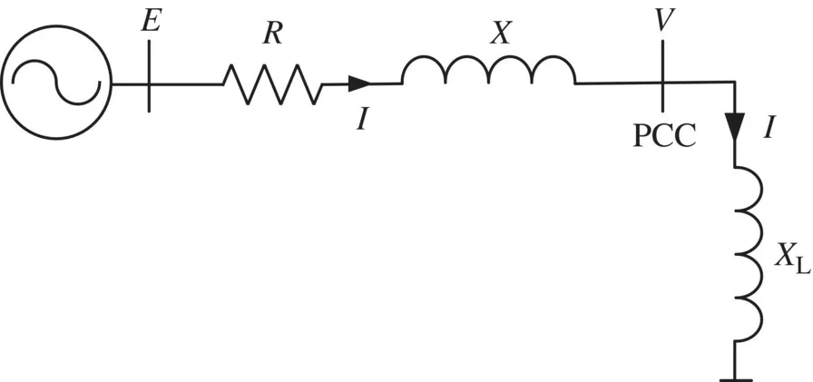
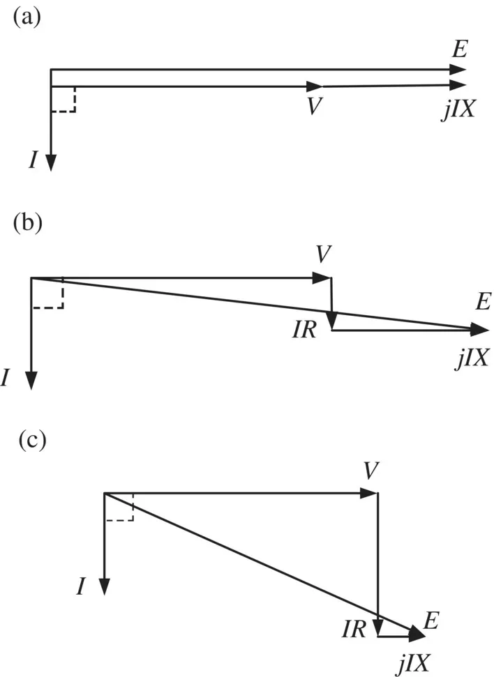
Injection of reactive power at a bus causes the voltage to rise whereas absorption of reactive power causes the bus voltage to decline. Figure 1.1 illustrates a simple power system having an equivalent voltage E and equivalent network short circuit impedance with reactance X and resistance R. An inductor XL is connected as load at a bus termed Point of Common Coupling (PCC) to show the effect of reactive power absorption. The PCC voltage and inductor current are denoted by V and I, respectively. The impact of reactive power absorption by the inductor on the PCC voltage is examined through phasor diagrams for three cases of network impedance. The phasor diagrams for cases (a) R = 0 (purely inductive network), (b) X/R = 3 (substantially reactive network), and (c) X/R = 1/3 (substantially resistive network) are depicted in Figure 1.2a–c, respectively. The phasor diagrams are drawn with the phasor V as reference, which has same magnitude in all the three cases. The phasor diagrams can also be drawn with equivalent voltage E as reference phasor having the same magnitude, although the conclusions will be the same in both cases.
Schematic illustration of a simple power system with an inductor connected at PCC.
Figure 1.1 A simple power system with an inductor connected at PCC.
Schematic illustration of phasor diagrams for network with inductive load; (a) network with R Equals 0; (b) network with X/R Equals 3; (c) network with X/R Equals 1/3.
Figure 1.2 Phasor diagrams for network with inductive load; (a) network with R = 0; (b) network with X/R = 3; (c) network with X/R = 1/3.
In the absence of inductor XL, the PCC voltage is E. The lagging inductor current causes a voltage drop IR + jIX across the network impedance, thereby reducing the PCC voltage to V. Stated alternately, the reactive power absorption by the inductor reduces PCC voltage by an amount |E| − |V |.
For case (a) R = 0, it is evident from Figure 1.2a that the change in voltage is directly proportional to network reactance and the magnitude of inductive current I (which in turn is dependent on the size of the bus inductor XL). Hence for same inductive current, the larger the network reactance, larger is the change in bus voltage. This also implies that higher reactive power absorption (corresponding to higher I) will cause a larger reduction in voltage in weak systems.
The impact of system X/R ratio is seen from Figure 1.2b corresponding to X/R = 3, and from Figure 1.2c relating to X/R = 1/3. The same amount of reactive current and reactive power absorption in inductor XL causes a larger voltage drop in the network with higher X/R ratio.
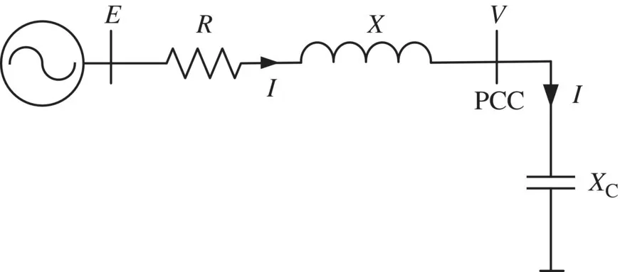
Schematic illustration of a simple power system with a capacitor connected at PCC.
Figure 1.3 A simple power system with a capacitor connected at PCC.
Consider a capacitor XC being connected as load at the PCC as depicted in Figure 1.3. The impact of reactive power injection by the capacitor on the PCC voltage is investigated through phasor diagrams for three cases of network impedance. The phasor diagrams for cases (i) R = 0 (purely inductive network), (ii) X/R = 3 (substantially reactive network), and (iii) X/R = 1/3 (substantially resistive network) are displayed in Figure 1.4a–c, respectively. In the absence of capacitor, the PCC voltage is E. The leading capacitor current causes a voltage drop IR + jIX across the impedance of the network, thereby increasing the PCC voltage to V. Stated alternately, the reactive power injection by capacitor increases the PCC voltage by an amount |V | − |E|.
The change in voltage due to capacitive load is thus directly proportional to network reactance and the magnitude of capacitive current I (which in turn is dependent on the size of the bus capacitor XC), as seen from Figure 1.4a. Hence for same capacitive current, the larger the network reactance, higher is the change in voltage. This also demonstrates that higher reactive power injection (corresponding to higher I) will cause a larger increase in voltage in weak systems.
The impact of system X/R ratio is observed from Figure 1.4b corresponding to X/R = 3, and from Figure 1.4c ...

Inhaltsverzeichnis