
eBook - ePub
Digital Signal Processing
Fundamentals and Applications
Li Tan
This is a test
Partager le livre
- 840 pages
- English
- ePUB (adapté aux mobiles)
- Disponible sur iOS et Android
eBook - ePub
Digital Signal Processing
Fundamentals and Applications
Li Tan
Détails du livre
Aperçu du livre
Table des matières
Citations
À propos de ce livre
This book will enable electrical engineers and technicians in the fields of the biomedical, computer, and electronics engineering, to master the essential fundamentals of DSP principles and practice. Coverage includes DSP principles, applications, and hardware issues with an emphasis on applications. Many instructive worked examples are used to illustrate the material and the use of mathematics is minimized for easier grasp of concepts.
In addition to introducing commercial DSP hardware and software, and industry standards that apply to DSP concepts and algorithms, topics covered include adaptive filtering with noise reduction and echo cancellations; speech compression; signal sampling, digital filter realizations; filter design; multimedia applications; over-sampling, etc. More advanced topics are also covered, such as adaptive filters, speech compression such as PCM, u-law, ADPCM, and multi-rate DSP and over-sampling ADC.
- Covers DSP principles and hardware issues with emphasis on applications and many worked examples
- End of chapter problems are helpful in ensuring retention and understanding of what was just read
Foire aux questions
Comment puis-je résilier mon abonnement ?
Il vous suffit de vous rendre dans la section compte dans paramètres et de cliquer sur « Résilier l’abonnement ». C’est aussi simple que cela ! Une fois que vous aurez résilié votre abonnement, il restera actif pour le reste de la période pour laquelle vous avez payé. Découvrez-en plus ici.
Puis-je / comment puis-je télécharger des livres ?
Pour le moment, tous nos livres en format ePub adaptés aux mobiles peuvent être téléchargés via l’application. La plupart de nos PDF sont également disponibles en téléchargement et les autres seront téléchargeables très prochainement. Découvrez-en plus ici.
Quelle est la différence entre les formules tarifaires ?
Les deux abonnements vous donnent un accès complet à la bibliothèque et à toutes les fonctionnalités de Perlego. Les seules différences sont les tarifs ainsi que la période d’abonnement : avec l’abonnement annuel, vous économiserez environ 30 % par rapport à 12 mois d’abonnement mensuel.
Qu’est-ce que Perlego ?
Nous sommes un service d’abonnement à des ouvrages universitaires en ligne, où vous pouvez accéder à toute une bibliothèque pour un prix inférieur à celui d’un seul livre par mois. Avec plus d’un million de livres sur plus de 1 000 sujets, nous avons ce qu’il vous faut ! Découvrez-en plus ici.
Prenez-vous en charge la synthèse vocale ?
Recherchez le symbole Écouter sur votre prochain livre pour voir si vous pouvez l’écouter. L’outil Écouter lit le texte à haute voix pour vous, en surlignant le passage qui est en cours de lecture. Vous pouvez le mettre sur pause, l’accélérer ou le ralentir. Découvrez-en plus ici.
Est-ce que Digital Signal Processing est un PDF/ePUB en ligne ?
Oui, vous pouvez accéder à Digital Signal Processing par Li Tan en format PDF et/ou ePUB ainsi qu’à d’autres livres populaires dans Technologie et ingénierie et Ingénierie de l'électricité et des télécommunications. Nous disposons de plus d’un million d’ouvrages à découvrir dans notre catalogue.
Informations
1
Introduction to Digital Signal Processing
Objectives
This chapter introduces concepts of digital signal processing (DSP) and reviews an overall picture of its applications. Illustrative application examples include digital noise filtering, signal frequency analysis, speech and audio compression, biomedical signal processing such as interference cancellation in electrocardiography, compact-disc recording, and image enhancement.
1.1 Basic Concepts of Digital Signal Processing
Digital signal processing (DSP) technology and its advancements have dramatically impacted our modern society everywhere. Without DSP, we would not have digital/Internet audio or video; digital recording; CD, DVD, and MP3 players; digital cameras; digital and cellular telephones; digital satellite and TV; or wire and wireless networks. Medical instruments would be less efficient or unable to provide useful information for precise diagnoses if there were no digital electrocardiography (ECG) analyzers or digital x-rays and medical image systems. We would also live in many less efficient ways, since we would not be equipped with voice recognition systems, speech synthesis systems, and image and video editing systems. Without DSP, scientists, engineers, and technologists would have no powerful tools to analyze and visualize data and perform their design, and so on.
The concept of DSP is illustrated by the simplified block diagram in Figure 1.1, which consists of an analog filter, an analog-to-digital conversion (ADC) unit, a digital signal (DS) processor, a digital-to-analog conversion (DAC) unit, and a reconstruction (anti-image) filter.
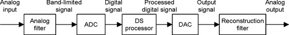
FIGURE 1.1 A digital signal processing scheme.
As shown in the diagram, the analog input signal, which is continuous in time and amplitude, is generally encountered in our real life. Examples of such analog signals include current, voltage, temperature, pressure, and light intensity. Usually a transducer (sensor) is used to convert the nonelectrical signal to the analog electrical signal (voltage). This analog signal is fed to an analog filter, which is applied to limit the frequency range of analog signals prior to the sampling process. The purpose of filtering is to significantly attenuate aliasing distortion, which will be explained in the next chapter. The band-limited signal at the output of the analog filter is then sampled and converted via the ADC unit into the digital signal, which is discrete both in time and in amplitude. The DS processor then accepts the digital signal and processes the digital data according to DSP rules such as lowpass, highpass, and bandpass digital filtering, or other algorithms for different applications. Notice that the DS processor unit is a special type of digital computer and can be a general-purpose digital computer, a microprocessor, or an advanced microcontroller; furthermore, DSP rules can be implemented using software in general.
With the DS processor and corresponding software, a processed digital output signal is generated. This signal behaves in a manner according to the specific algorithm used. The next block in Figure 1.1, the DAC unit, converts the processed digital signal to an analog output signal. As shown, the signal is continuous in time and discrete in amplitude (usually a sample-and-hold signal, to be discussed in Chapter 2). The final block in Figure 1.1 is designated as a function to smooth the DAC output voltage levels back to the analog signal via a reconstruction (anti-image) filter for real-world applications.
In general, the analog signal process does not require software, an algorithm, ADC, and DAC. The processing relies wholly on electrical and electronic devices such as resistors, capacitors, transistors, operational amplifiers, and integrated circuits (ICs).
DSP systems, on the other hand, use software, digital processing, and algorithms; thus they have a great deal of flexibility, less noise interference, and no signal distortion in various applications. However, as shown in Figure 1.1, DSP systems still require minimum analog processing such as the anti-aliasing and reconstruction filters, which are musts for converting real-world information into digital form and digital form back into real-world information.
Note that there are many real-world DSP applications that do not require DAC, such as data acquisition and digital information display, speech recognition, data encoding, and so on. Similarly, DSP applications that need no ADC include CD players, text-to-speech synthesis, and digital tone generators, among others. We will review some of them in the following sections.
1.2 Basic Digital Signal Processing Examples in Block Diagrams
We first look at digital noise filtering and signal frequency analysis, using block diagrams.
1.2.1 Digital Filtering
Let us consider the situation shown in Figure 1.2, depicting a digitized noisy signal obtained from digitizing analog voltages (sensor output) containing a useful low-frequency signal and noise that occupies all of the frequency range. After ADC, the digitized noisy signal x(n), where n is the sample number, can be enhanced using digital filtering.

FIGURE 1.2 The simple digital filtering block.
Since our useful signal contains the low-frequency component, the high-frequency components above that of our useful signal are considered as noise, which can be removed by using a digital lowpass filter. We set up the DSP block in Figure 1.2 to operate as a simple digital lowpass filter. After processing the digitized noisy signal x(n), the digital lowpass filter produces a clean digital signal y(n). We can apply the cleaned signal y(n) to another DSP algorithm for a different application or convert it to the analog signal via DAC and the reconstruction filter.
The digitized noisy signal and clean digital signal, respectively, are plotted in Figure 1.3, where the top plot shows the digitized noisy signal, while the bottom plot dem...