Technology & Engineering
Boolean Algebra
Boolean algebra is a mathematical system used to analyze and simplify digital circuits. It deals with variables that can have only two possible values, typically represented as 0 and 1. The algebraic operations in Boolean algebra include AND, OR, and NOT, which are used to manipulate and simplify logical expressions. It forms the foundation for digital logic design and is essential in computer science and engineering.
Written by Perlego with AI-assistance
Related key terms
1 of 5
10 Key excerpts on "Boolean Algebra"
 eBook - PDF
- Dale R. Patrick, Stephen W. Fardo, Vigyan Chandra(Authors)
- 2020(Publication Date)
- River Publishers(Publisher)
Chapter 3 Boolean Algebra and Logic Gates INTRODUCTION Digital electronics operates on a mathematical base as do other forms of electronics. The operating principle of a digital electronic system is quite unique when compared with other electronic functions. Digital electron-ics, for example, is concerned with two-state information represented by bits. A bit may assume either one of two values: 0 or 1. The operational base of this system is considered to be binary, or base 2. Boolean Algebra is the mathematical basis of digital logic because it responds to base 2 infor-mation. Boolean Algebra is an important tool when used in the digital elec-tronics field. It is used to express logic functions in the form of an equa-tion, to analyze data, to simplify logic expressions, to design logic circuits and to troubleshoot a logic circuit. A person working with digital logic cir-cuits continually uses Boolean Algebra. USING Boolean Algebra In 1854 George Boole, an Englishman, published a paper titled “An Investigation of the Laws of Thought.” In this publication, Boole symbol-ized the form of algebra that deals with two-state logic. In 1938 Claude Shannon, an American, wrote a paper titled “A Symbolic Analysis of Relay and Switching Circuits.” This paper applied Boole’s ideas to relay switch-ing used in telephone circuitry. Today, this is called Boolean Algebra. It is based on standard algebraic principles that deal with the mathematical theory of two-state logic. The notations of Boolean Algebra and theorems are fundamental in the study of digital electronics. Boolean Algebra is a special form of algebra that was designed to show the relationships of two-state variable logic operations. 49 50 Electronic Digital System Fundamentals This form of algebra is ideally suited for the analysis and design of binary logic systems. Through the use of Boolean Algebra, it is possible to write mathematical expressions that describe specific logic functions. eBook - PDF
Digital Computer Design
Logic, Circuitry, and Synthesis
- Edward L. Braun(Author)
- 2014(Publication Date)
- Academic Press(Publisher)
3. Boolean Algebra 3.1. Introduction The subject of Boolean Algebra has important application in the design of systems composed of storage elements capable of assuming a discrete number of stable states and switching devices that trigger these elements from one stable state to another. An electronic digital computer is such a system. The utility of Boolean Algebra in the design of digital equipment will be better appreciated after the discussion in this chapter of certain fundamentals, including a comparison of ordinary algebra and Boolean Algebra, procedures for simplifying Boolean Algebraic equations, and the basis for representing switching functions in binary computers by Boolean Algebraic equations. Algebra ordinarily refers to that branch of mathematics wherein quantitative relationships between entities are indicated by the use of numbers, letters (as symbols for the entities), and operational symbols (such as multiplication or addition signs). The rules of arithmetic are used in the solution of such algebraic equations. The ways in which Boolean Algebra differs from ordinary algebra are summarized below: (1) There are no coefficients associated with the terms in a Boolean Algebraic equation. (2) Each letter designates which of two distinguishable events exists. As a matter of convenience, the value assigned to the letter upon the occurrence of one event is 0, and for the other it is 1. (3) A Boolean Algebraic function can only state whether one of two possible events exists, e.g., whether a circuit is open or closed, a signal present or not, a statement true or false, etc. The two possible values of the function are also usually designated by 0 and 1. (4) There are a number of logical operators for producing Boolean Algebraic functions. However, in general, they are not all used in the logical description of a digital computer for any Boolean function can be generated by the use of a proper subset of these operators. eBook - PDF
- Darrell H. Abney, Laurence Rubin, Donald W. Sibrel(Authors)
- 2014(Publication Date)
- Academic Press(Publisher)
8 Boolean Algebra 8.0 Introduction Today, to many people, Boolean Algebra means computer algebra. But this has been true only since the late 1940s when digital computers started to become practical. The founder of mathematical logic was George Boole (1815-1864), an English mathematician. In 1847, 100 years before electronic computers, he published his Mathematical Analysis ofLogic. In 1938 Claude Shannon applied the principles of Boole to switching circuits. Today digital computers use electronic switching circuits to perform the many arithmetic and logical operations required in the solutions of problems and the processing of data. Nearly all these circuits are formed from three basic types: AND, OR, and NOT. The circuit operations can be described by simple expressions of a specialized logic called Boolean Algebra. 159 To fully understand computers, we must understand computer logic, that is, Boolean Algebra. If one can simplify a Boolean expression, then one can simplify the computer logic used to solve a problem. This could mean that either the number of circuit components could be reduced or a computer program could be shortened and simplified. This would be a savings in both time and money. The physical and electrical properties of electronic components dictate that information can be most efficiently stored in a computer in binary form. This means that the smallest piece of information, the bit, can be only one of two values. We call them 0 or 1. Inside the computer it could be current either flowing or not flowing, a voltage either high or low, or a magnetic bit polarized in either one direction or another. We will see there is a strong tie between Boolean Algebra and what we have learned in set theory and logic. In Section 8.2, simplifying Boolean expressions, we will use Boolean tables, which are very similar to truth tables. In Section 8.3, we will use Veitch diagrams, which are similar to the Venn diagrams used in set theory. No longer available |Learn more
- (Author)
- 2014(Publication Date)
- White Word Publications(Publisher)
________________________ WORLD TECHNOLOGIES ________________________ Chapter-1 Boolean Algebra Boolean Algebra , as developed in 1854 by George Boole in his book An Investigation of the Laws of Thought , is a variant of ordinary elementary algebra differing in its values, operations, and laws. Instead of numbers, Boole's algebra operates on the truth values 0 and 1. The operations are usually taken to be conjunction ∧ , disjunction ∨ , and negation ¬, with constants 0 and 1. And the laws are definable as those equations that hold for all values of their variables, for example x ∨ ( y ∧ x ) = x . Applications include mathematical logic, digital logic, computer programming, se t theory, and statistics. Boole's algebra predated the modern developments in abstract algebra and mathematical logic; it is however seen as connected to the origins of both fields. In an abstract setting, Boolean Algebra was perfected in the late 19th cen tury by Jevons, Schröder, Huntington, and others until it reached the modern conception of an (abstract) mathematical structure. For example, the empirical observation that one can manipulate expressions in the algebra of sets by translating them into expr essions in Boole's algebra is explained in modern terms by saying that the algebra of sets is a Boolean Algebra (note the indefinite article). In the 1930s, while studying switching circuits, Claude Shannon observed that one could also apply the rules of B oole's algebra in this setting, and he introduced switching algebra as a way to analyze and design circuits by algebraic means in terms of logic gates. Shannon already had at his disposal the abstract mathematical apparatus, thus he cast his switching algebra as the two -element Boolean Algebra. In circuit engineering settings today, there is little need to consider other Boolean Algebras, thus switching algebra and Boolean Algebra are often used interchangeably. No longer available |Learn more
- (Author)
- 2014(Publication Date)
- Library Press(Publisher)
________________________ WORLD TECHNOLOGIES ________________________ Chapter 6 Introduction to Boolean Algebra Boolean Algebra , as developed in 1854 by George Boole in his book An Investigation of the Laws of Thought , is a variant of ordinary elementary algebra differing in its values, operations, and laws. Instead of the usual algebra of numbers, Boolean Algebra is the algebra of truth values 0 and 1, or equivalently of subsets of a given set. The operations are usually taken to be conjunction ∧ , disjunction ∨ , and negation ¬, with constants 0 and 1. And the laws are definable as those equations that hold for all values of their variables, for example x ∨ ( y ∧ x ) = x . Applications include mathematical logic, digital logic, computer programming, set theory, and statistics. Boole's algebra predated the modern developments in abstract algebra and mathematical logic; it is however seen as connected to the origins of both fields. In an abstract setting, Boolean Algebra was perfected in the late 19th century by Jevons, Schröder, Huntington, and others until it reached the modern conception of an (abstract) mathematical structure. For example, the empirical observation that one can manipulate expressions in the algebra of sets by translating them into expressions in Boole's algebra is explained in modern terms by saying that the algebra of sets is a Boolean Algebra (note the indefinite article). In fact, M. H. Stone proved in 1936 that every Boolean Algebra is isomorphic to a field of sets. In the 1930s, while studying switching circuits, Claude Shannon observed that one could also apply the rules of Boole's algebra in this setting, and he introduced switching algebra as a way to analyze and design circuits by algebraic means in terms of logic gates. Shannon already had at his disposal the abstract mathematical apparatus, thus he cast his switching algebra as the two-element Boolean Algebra. No longer available |Learn more
- (Author)
- 2014(Publication Date)
- Library Press(Publisher)
________________________ WORLD TECHNOLOGIES ________________________ Chapter 8 Introduction to Boolean Algebra Boolean Algebra , as developed in 1854 by George Boole in his book An Investigation of the Laws of Thought , is a variant of ordinary elementary algebra differing in its values, operations, and laws. Instead of the usual algebra of numbers, Boolean Algebra is the algebra of truth values 0 and 1, or equivalently of subsets of a given set. The operations are usually taken to be conjunction ∧ , disjunction ∨ , and negation ¬, with constants 0 and 1. And the laws are definable as those equations that hold for all values of their variables, for example x ∨ ( y ∧ x ) = x . Applications include mathematical logic, digital logic, computer programming, set theory, and statistics. Boole's algebra predated the modern developments in abstract algebra and mathematical logic; it is however seen as connected to the origins of both fields. In an abstract setting, Boolean Algebra was perfected in the late 19th century by Jevons, Schröder, Huntington, and others until it reached the modern conception of an (abstract) mathematical structure. For example, the empirical observation that one can manipulate expressions in the algebra of sets by translating them into expressions in Boole's algebra is explained in modern terms by saying that the algebra of sets is a Boolean Algebra (note the indefinite article). In fact, M. H. Stone proved in 1936 that every Boolean Algebra is isomorphic to a field of sets. In the 1930s, while studying switching circuits, Claude Shannon observed that one could also apply the rules of Boole's algebra in this setting, and he introduced switching algebra as a way to analyze and design circuits by algebraic means in terms of logic gates. Shannon already had at his disposal the abstract mathematical apparatus, thus he cast his switching algebra as the two-element Boolean Algebra.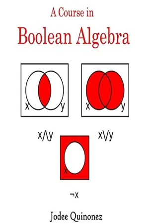 No longer available |Learn more
- (Author)
- 2014(Publication Date)
- Learning Press(Publisher)
________________________ WORLD TECHNOLOGIES ________________________ Chapter- 1 Introduction to Boolean Algebra Boolean Algebra , as developed in 1854 by George Boole in his book An Investigation of the Laws of Thought , is a variant of ordinary elementary algebra differing in its values, operations, and laws. Instead of the usual algebra of numbers, Boolean Algebra is the algebra of truth values 0 and 1, or equivalently of subsets of a given set. The operations are usually taken to be conjunction ∧ , disjunction ∨ , and negation ¬, with constants 0 and 1. And the laws are definable as those equations that hold for all values of their variables, for example x ∨ ( y ∧ x ) = x . Applications include mathematical logic, digital logic, computer programming, set theory, and statistics. Boole's algebra predated the modern developments in abstract algebra and mathematical logic; it is however seen as connected to the origins of both fields. In an abstract setting, Boolean Algebra was perfected in the late 19th century by Jevons, Schröder, Huntington, and others until it reached the modern conception of an (abstract) mathematical structure. For example, the empirical observation that one can manipulate expressions in the algebra of sets by translating them into expressions in Boole's algebra is explained in modern terms by saying that the algebra of sets is a Boolean Algebra (note the indefinite article). In fact, M. H. Stone proved in 1936 that every Boolean Algebra is isomorphic to a field of sets. In the 1930s, while studying switching circuits, Claude Shannon observed that one could also apply the rules of Boole's algebra in this setting, and he introduced switching algebra as a way to analyze and design circuits by algebraic means in terms of logic gates. Shannon already had at his disposal the abstract mathematical apparatus, thus he cast his switching algebra as the two-element Boolean Algebra.
- Charles Roth, Jr., Larry Kinney, Eugene John, , Charles Roth, Jr., Larry Kinney, Eugene John(Authors)
- 2020(Publication Date)
- Cengage Learning EMEA(Publisher)
One definition of Boolean Algebra is a set containing at least two distinct elements with the operations of AND, OR, and complement defined on the elements that satisfy X Y X uni2032 Y uni2032 X + Y (X + Y )uni2032 X uni2032Y uni2032 XY (XY )uni2032 X uni2032 + Y uni2032 0 0 1 1 0 1 1 0 1 1 0 1 1 0 1 0 0 0 1 1 1 0 0 1 1 0 0 0 1 1 1 1 0 0 1 0 0 1 0 0 Copyright 2021 Cengage Learning. All Rights Reserved. May not be copied, scanned, or duplicated, in whole or in part. Due to electronic rights, some third party content may be suppressed from the eBook and/or eChapter(s). Editorial review has deemed that any suppressed content does not materially affect the overall learning experience. Cengage Learning reserves the right to remove additional content at any time if subsequent rights restrictions require it. 46 Unit 2 the laws in Table 2-3. This definition is not minimal (i.e., the laws are not independent since some can be derived from others). It is chosen for convenience so that other Boolean Algebra theorems can be derived easily. One minimal set of laws referred to as Huntington’s postulates are operations with 0 and 1, commutative laws, distribu- tive laws, and complementation laws. The other laws can be algebraically derived from this minimal set. The Boolean Algebra laws were given in pairs to show the algebra satisfies a dual- ity. Given a Boolean Algebra expression the dual of the expression is obtained by interchanging the constants 0 and 1 and interchanging the operations of AND and OR. Variables and complements are left unchanged. The laws listed in Table 2-3 show that given a Boolean Algebra identity, another identity can be obtained by taking the dual of both sides of the identity. The dual of AND is OR and the dual of OR is AND: (XYZ. . .) D = X + Y + Z + · · · (X + Y + Z + · · ·) D = XYZ. eBook - PDF
- Bernd Steinbach, Christian Posthoff(Authors)
- 2022(Publication Date)
- Springer(Publisher)
1 C H A P T E R 1 Basics of the Binary Boolean Algebra 1.1 INTRODUCTION We start this chapter with a short presentation of the concepts of the binary Boolean Algebra. Each reader should check his knowledge, particularly the knowledge of the different operation symbols and the applicable rules for the respective operations. Particularly the knowledge of the antivalence and the equivalence is very important, as it might not be as well known as the conjunction, the disjunction, and the negation (the complement ). Boolean equations and systems of Boolean equations are an important and elegant possibility to build models for very different problems. Here it is necessary to study the different solution methods. These solution methods are supported by the use of the XBOOLE system. It should be understood as an implementation and a summary of Numerical Methods for the binary Boolean Algebra. For larger numbers of variables where it is absolutely impossible to solve the problems “by hand,” XBOOLE is a comfortable support for all necessary calculations. This includes also the operations of the Boolean Differential Calculus which will be introduced in the next chapter. It is necessary to be on the safe side when using this system. 1.2 BOOLEAN SPACE, BOOLEAN FUNCTIONS, AND OPERATIONS In this chapter we repeat the basic concepts of the binary Boolean Algebra based on the set B = {0, 1} with the two distinct elements 0 and 1. In technical applications 0 and 1 will be used all the time; in logics and in programming languages we also find true or t being used instead of 1 and false or f instead of 0. This will be indicated, if necessary, along with the respective applications. eBook - PDF
Discrete Mathematics
Proofs, Structures and Applications, Third Edition
- Rowan Garnier, John Taylor(Authors)
- 2009(Publication Date)
- CRC Press(Publisher)
Chapter 10 Boolean Algebra 10.1 Introduction In chapter 3 we noted the strong similarity between the algebra of sets and that of propositions. In particular, each of the laws listed in §3.5 has a counterpart in §1.5 to which it bears more than a passing resemblance. For example, De Morgan’s laws for the propositions p and q are given by p ∨ q ≡ ¯ p ∧ ¯ q and p ∧ q ≡ ¯ p ∨ ¯ q . For the sets A and B these laws take the form ( A ∪ B ) = ¯ A ∩ ¯ B and ( A ∩ B ) = ¯ A ∪ ¯ B . In this chapter we shall see that the laws common to these two systems are attributable to their relationship to an algebraic structure known as a ‘Boolean Algebra’ and that the properties which they share are those which are common to all Boolean Algebras. The idea of a Boolean Algebra was first developed by George Boole † in the middle of the nineteenth century. Boole was chiefly concerned with the algebra of propositions but, in recent years, the subject has been extended and is now a significant component of abstract algebra. An important application of Boolean Algebra is in the analysis of electronic circuits and hence in the design of a range of digital devices such as computers, telephone systems and electronic control systems. † Boole’s book The Laws of Thought published in 1854 was an attempt to formalize the process of logical thinking. 492 Introduction 493 Definition 10.1 A Boolean Algebra consists of a set B together with three operations defined on that set. These are: (a) a binary operation denoted by ⊕ referred to as the sum (or join ); (b) a binary operation denoted by * referred to as the product (or meet ); (c) an operation which acts on a single element of B , denoted by ¯ , where, for any element b ∈ B , the element ¯ b ∈ B is called the complement of b . (An operation which acts on a single member of a set S and which results in a member of S is called a unary operation .) The following axioms apply to the set B together with the operations ⊕ , * and ¯ .
Index pages curate the most relevant extracts from our library of academic textbooks. They’ve been created using an in-house natural language model (NLM), each adding context and meaning to key research topics.