Technology & Engineering
Creep Rupture
Creep rupture refers to the failure of a material under constant stress at high temperatures over an extended period. It is a time-dependent phenomenon that occurs in materials such as metals and alloys, and is characterized by the gradual deformation and eventual fracture of the material. Creep rupture is a critical consideration in the design and operation of high-temperature components in engineering applications.
Written by Perlego with AI-assistance
Related key terms
1 of 5
8 Key excerpts on "Creep Rupture"
 eBook - PDF
- J.T. Boyle, J. Spence(Authors)
- 2013(Publication Date)
- Butterworth-Heinemann(Publisher)
Chapter 9 Creep Rupture So far, we have only dealt with the calculation of stresses and distortions in a creeping structure (using either direct numerical techniques or simplified methods). Nevertheless, the ultimate aim in design for creep is the avoidance of structural failure during the expected life of a component. The question is — can we use the type of information that we already have to predict the lifetime of a structure? In order to attempt to resolve this question, it is necessary to under-stand the fundamental failure mechanisms which can occur due to creep. It is the purpose of this chapter to examine in detail one such mechanism, Creep Rupture, which can lead to a fracture of the structure causing a loss in load-bearing capacity. As we have seen in Section 2.4, the creep process in a material will ultimately lead to Creep Rupture either through a ductile mechanism induced by large strains or through material embrittlement. Arguably the most insidious failure mechanism is the latter, which can occur at low strains. This will be examined in more detail here. 9.1 Constitutive equations for Creep Rupture The material deterioration in a metal at elevated temperature which causes embrittlement proceeds mainly due to the nucleation and growth of fissures and voids on a microscopic level. The presence of such defects is loosely termed damage in the material. For a proper understanding of creep damage and its generalisation to multiaxial stress states, some description of the physical processes involved is necessary. This has been avoided so far with the adoption of a phenomenological approach. However, both a phenomenological and physical interpretation of damage is possible: these are outlined below. 9.1,1 Phenomenological approach The notion of damage in a phenomenological context is only very vague. It can be introduced into a mathematical model of the creep process in one of two ways. eBook - ePub
Engineering Physics of High-Temperature Materials
Metals, Ice, Rocks, and Ceramics
- Nirmal K. Sinha, Shoma Sinha(Authors)
- 2022(Publication Date)
- Wiley(Publisher)
6 Phenomenological Creep Failure ModelsCHAPTER MENU
- 6.1 Creep and Creep Failure
- 6.2 Steady-State Creep
- 6.3 Commonly Used Creep Experiments and Strength Tests
- 6.3.1 Constant Stress and Constant Deformation (CD) Rate Tests
- 6.3.2 A Short Glimpse of Creep Tests
- 6.3.3 Power Law for Creep
- 6.3.4 Larsen and Miller Concept
- 6.3.5 Monkman and Grant (M-G) Relationship
- 6.3.6 Rabotnov–Kachanov Concept for Creep Fracture
- 6.3.7 Breaking Tradition – θ-Projection Concept
- 6.4 Modeling Very Long-Term Creep Rupture from Short-Term Tests
- 6.4.1 Traditional Approaches for Power-Generation Operations
- 6.4.2 Captivating and Entrenched Focus on Minimum Creep Rate
- 6.5 High-Temperature Low-Cycle Fatigue (HT-LCF) and Dwell Fatigue
- 6.6 Crucial Tests on Rate Sensitivity of High-Temperature Strength
- 6.7 Rational Approach Inspired by the Principle of “Hindsight 20/20”
- References
6.1 Creep and Creep Failure
High‐temperature engineering problems require solutions in terms of specific design stress, strain, and/or structural damage limits. Engineers must know the material characteristics or the interdependence between stress, strain, damage state, and time for a given component at a given temperature distribution and loading or deformation history. To improve the efficiency of high‐temperature equipment, such as that in power‐generating systems and jet engines, the requirement is to increase the operating temperature. As the operating temperatures are increased, environmental issues affecting the structural components start playing important roles.An engineering structure or component can be designed to function properly and achieve the required life under specified operating conditions without failure if the creep, creep damage, and fracture characteristics of a material are known. Creep and fracture of natural or manufactured metals and alloys is part of a larger field of study, such as the deformation and failure of all polycrystalline solids. As the temperature increases from the usual “room temperature,” “ordinary,” or “normal” temperatures of about 0.1 T m (to be called “low”), to temperatures greater than about 0.3Tm(to be called “high”), the total strain can be described phenomenologically in terms of three major components, which have already been introduced in Chapter 1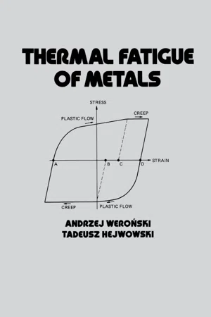 eBook - PDF
- Andrzej Weronski(Author)
- 1991(Publication Date)
- CRC Press(Publisher)
Creep 2 2.1 INTRODUCTION The term creep denotes slowly proceeding deformation of solid matter under a maintained load. The first systematic studies providing some quantitative informa-tion on the nature of creep were those of Andrade (1910). During World War I, research on creep became more urgent. Impetus was given by the rapid increase in steam admission temperatures in power plants (to about 670 K in the 1920s), approaching the creep range of low-alloy steels. Early researchers were concerned with finding the limiting stress below which creep would not occur, but using more accurate experimental techniques, this idea was subsequently shown to be false. The temperature at which creep becomes important for the designer is about 0.4 of the melting temperature of the material considered, but numerous exceptions bring this rule into question. For example, creep is observed in titanium at lower temperatures than in iron-based alloys, despite the higher melting point of the former. Stress levels under which creep is observable are always much lower than the strength of the material. A creep curve, which is the graphical presentation of the dependence of the strain on time under constant stress and temperature, is shown in Fig. 2.1. The strain £ 0 is developed immediately upon loading; the period of time between £ 0 and is called primary creep. Between ex and e2 the creep rate remains almost constant; this portion of the curve is termed secondary (or steady-state) creep: • * 2 S i £f = -----h ~ h The creep rate increases beyond £ 2 » an<3 this period is called tertiary creep. It is convenient to obtain experimental data under a constant tensile load. As creep proceeds, the true stress increases continually, giving rise to a pronounced change in the creep rate. The tertiary creep, where necking is appreciable, is certainly also 54 Creep 55 Time Figure 2.1 Schematic representation of a creep-rupture curve. eBook - ePub
Deformation and Evolution of Life in Crystalline Materials
An Integrated Creep-Fatigue Theory
- Xijia Wu(Author)
- 2019(Publication Date)
- CRC Press(Publisher)
CHAPTER 5 Creep 5.1 OverviewCreep refers to the phenomena of time-dependent deformation under constant load or stress at elevated temperature. Following Andrade’s first observation in 1910, creep testing has been a conventional way to characterize material’s high-temperature strength. A typical uniaxial creep frame setup is shown in Figure 5.1 , where the creep coupon is loaded by a dead weight through a lever arm. Such a creep test is therefore called constant-load creep test. During the test, the coupon is enclosed in a furnace set at temperature and its elongation is measured using a linear variable differential transformer (LVDT). The elongation-time data are recorded to the point of specimen fracture, i.e., stress rupture, and hence creep life is called the rupture life.Figure 5.1. Schematic drawing of main components of creep testing machine (after Bueno, 2008).Creep deformation as high-temperature design limitations is widely recognized in industrial design codes, e.g., ASME Boiler and Pressure Vessel Code. The creep failure criteria can be given either in terms of creep strain to be reached, e.g. 1%, or hours of service, e.g. 100,000 hours, against which the allowable stress is determined. With regards to the above criteria for component design, a few questions and factors have to be completely understood. eBook - PDF
- Marc André Meyers, Krishan Kumar Chawla(Authors)
- 2008(Publication Date)
- Cambridge University Press(Publisher)
Chapter 13 Creep and Superplasticity 13.1 Introduction The technological developments wrought since the early twenti-eth century have required materials that resist higher and higher temperatures. Applications of these developments lie mainly in the following areas: 1. Gas turbines (stationary and on aircraft), whose blades operate at temperatures of 800--950 K. The burner and afterburner sections operate at even higher temperatures, viz. 1,300--1,400 K. 2. Nuclear reactors, where pressure vessels and piping operate at 650--750 K. Reactor skirts operate at 850--950 K. 3. Chemical and petrochemical industries. All of these temperatures are in the range (0.4--0.65) T m , where T m is the melting point of the material in kelvin. The degradation undergone by materials in these extreme condi-tions can be classified into two groups: 1. Mechanical degradation . In spite of initially resisting the applied loads, the material undergoes anelastic deformation; its dimen-sions change with time. 2. Chemical degradation . This is due to the reaction of the material with the chemical environment and to the diffusion of external elements into the materials. Chlorination (which affects the prop-erties of superalloys used in jet turbines) and internal oxidation are examples of chemical degradation. This chapter deals exclusively with mechanical degradation. The time-dependent deformation of a material is known as creep . A great num-ber of high-temperature failures can be attributed either to creep or to a combination of creep and fatigue. Creep is characterized by a slow flow of the material, which behaves as if it were viscous. If a mechan-ical component of a structure is subjected to a constant tensile load, the decrease in cross-sectional area (due to the increase in length resulting from creep) generates an increase in stress; when the stress 654 CREEP AND SUPERPLASTICITY reaches the value at which failure occurs statically (ultimate tensile stress), failure occurs.
- John K Tien(Author)
- 2012(Publication Date)
- Academic Press(Publisher)
11 Creep and Stress Rupture—Long Term YOSHIO MONMA National Research Institute for Metals (NRIM) Tokyo, Japan I. Introduction 339 II. Data Sources 340 III. Evaluation of Creep-Rupture Data 341 A. Time-Temperature Parameter Methods for Stress Rupture Curves 341 B. Examples of TTP Correlation and Extrapolation 343 C. Determination of Parameter Constant from Chemical Composition 348 D. Correlation to Long-Time Strength 352 IV. Strain-Time Behavior 355 A. Creep Curves 355 B. Effect of Processing 355 C. Minimum Creep Rate and Time to Tertiary Creep 356 V. Microstructural Stability and Ductility Consideration 359 VI. Conclusion 360 Acknowledgment 360 References 360 I. INTRODUCTION A material subjected under stress at high temperature suffers gradual deformation and degradation. Most notably, the creep deformation and the microstructural changes occur with time. Although the behavior of superal-loys at elevated temperatures attracted many researchers/engineers, there are always questions about the long term strength and the stability of microstruc-ture. This chapter deals with the Creep Rupture strength and the creep strain-time behavior of typical superalloys. For more than 20 years the NRIM has conducted an extensive testing program to generate systematic creep data on about 40 kinds of heat-resisting steels and alloys. The total number of heats/casts is about 370. This program is called NRIM Creep Data Sheet Program (NRIM/CDS). About 70 data points with the rupture times beyond 100,000h are available from the program. Several superalloys were sampled in the program and have been SUPERALLOYS, SUPERCOMPOSITES 339 Copyright © 1989 by Academic Press, Inc. and SUPERCERAMICS All rights of reproduction in any form reserved. ISBN 0-12-690845-1 340 YOSHIO MONMA subjected to long-time tests typically up to 50,000h. The primary method to evaluate creep data are TTP (time-temperature parameter) methods based on the theory of the thermally activated rate process [1]. eBook - ePub
Materials Ageing and Degradation in Light Water Reactors
Mechanisms and Management
- K L Murty, K. L. Murty(Authors)
- 2013(Publication Date)
- Woodhead Publishing(Publisher)
3Creep deformation of materials in light water reactors (LWRs)
K.L. Murty, North Carolina State University, USAS. Gollapudi, Massachusetts Institute of Technology, USAK. Ramaswamy, Bhabha Atomic Research Center, IndiaM.D. Mathew, Indira Gandhi Center for Atomic Research, IndiaI. Charit, University of Idaho, USAAbstract:
The time-dependent deformation of materials or creep governs the useful life of many engineering structures. It assumes even higher significance in the case of structures constituting a nuclear reactor, wherein materials bombarded with neutrons develop defects that assist faster diffusion leading to greater plastic deformation. As a result, an understanding of the creep deformation process and factors controlling it is necessary for gauging the usefulness of materials in a nuclear reactor as well as for predicting life-times of various structures. Thus in this work we discuss the various mechanisms of creep, the rate controlling factors, deformation mechanism maps and useful life prediction methodologies. We also identify a few cases where direct application of simple creep correlations might not be feasible. Finally, we discuss the various factors that control the creep behavior of materials in light water reactors.Key words creep diffusion creep dislocation creep deformation mechanism maps modeling zirconium alloys stainless steels irradiation creep3.1 Introduction
Creep is time-dependent plastic strain under a constant load/stress at a given temperature and often becomes the life limiting criterion for many structures that experience loads and temperatures, and becomes significant for materials in light water reactors (LWRs) due to imposed radiation effects. A thorough understanding of the plastic deformation behavior of materials is essential for the sound design of engineering structures. Fail-safe designs are based on the ability to predict the response of a structure to applied loads and ensuing plastic deformation. While brittle materials such as ceramics fail after relatively low plastic strains, a significant number of engineering materials such as metals and alloys are characterized by large scale plastic deformation leading to failure. The extent of deformation is controlled by intrinsic factors such as bond strength, presence of secondary phases and defect concentration. At the same time extrinsic factors such as applied loads, temperature, deformation rates and geometry of the structure also determine the amount of plastic deformation. It has been well established that high applied loads and temperatures generally accelerate the rate of plastic deformation. This is because high temperatures and stresses provide the necessary activation energy required for defects to overcome barriers to plastic deformation. While plastic deformation at room temperature or low homologous temperatures (T /Tm) occurs when the applied stress exceeds the yield stressσy
- David C. Cranmer, David W. Richerson(Authors)
- 1998(Publication Date)
- CRC Press(Publisher)
However, he ruled out creep frac ture due to the small measured strains at failure. From the results and discussion presented above, it is apparent that the size of the processing defects that exist in the SCRB210 tubes is the main variable controlling the design criteria. Creep was not the limiting design criterion for the SCRB210 tubular components since the stress levels which can be applied to these components, without causing immediate failure, are small and therefore will not induce appreciable creep rates. Instead, another delayed failure mechanism, crack growth, is responsible for the time-depen- dent failure of the SCRB210 tubes. Such crack growth could not have oc curred at such low stress levels had the defects been smaller in size. The relationship between the delayed failure mode (SCG or creep rup ture) and component size (directly related to inherent flaw sizes) is shown schematically in Fig. 7.20. Note that the stress rupture curve, when delayed failure is controlled by SCG, shifts to lower applied stress levels as the component sizes/defect sizes increase, as was shown previously in Section 7.3.1 when the stress rupture curve for the SASC tensile specimens was projected to predict the stress rupture curve for the SASC tubes. However, the Creep Rupture curve is unique for all component sizes. Therefore, for a given applied stress level (horizontal line), the delayed failure mode would change from SCG for the tubular components to Creep Rupture for the tensile specimens. Unfortunately, at the present time, the SCG parameters for the SCRB210 material are not available, thus precluding further analysis to pre dict the lifetimes for the tubes based on SCG delayed failure analysis. 7.4. EVALUATION OF THE THERMOMECHANICAL PERFORMANCE FOR CERAMIC RADIANT TUBES Radiant tubes are used in industrial heating processes that require isolation of the workload or furnace charge from the combustion byproducts.
Index pages curate the most relevant extracts from our library of academic textbooks. They’ve been created using an in-house natural language model (NLM), each adding context and meaning to key research topics.