Perspective, the author tells us, is easy; yet surprisingly few artists are aware of the simple rules that make it so. This easy-to-follow book — the first devoted entirely to clarifying the laws of perspective — remedies the situation. In it, the author uses over 250 simple line drawings to illustrate the concepts involved.
Beginning with clear, concise, immediately applicable discussions of the horizon, vanishing point, and the crucial relationship of eye level to perspective drawing, you'll learn how to place figures and objects in a drawing, depict interiors, create shade and shadows, and achieve all the other elements necessary for a successful perspective drawing. By repeatedly stressing important points, Mr. Norling teaches you to make them second-nature. Moreover, his approach is so simple and direct that no matter how little raw talent or experience you have, you will soon be able to apply these techniques almost instinctively.
Mastery of perspective is a basic skill every artist must have. This simple, nontechnical guide will enable you to master its essentials in a relatively short time. Clear and concise, this book is an essential addition to any artist's bookshelf.
- 224 pages
- English
- ePUB (mobile friendly)
- Available on iOS & Android
eBook - ePub
Perspective Made Easy
About this book
Trusted by 375,005 students
Access to over 1.5 million titles for a fair monthly price.
Study more efficiently using our study tools.
Information
Topic
ArtSubtopic
Art TechniquesSTEP TWENTY
MECHANICAL PERSPECTIVE
MECHANICAL PERSPECTIVE
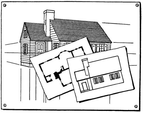
We have been learning about perspective as we would use it in sketching and freehand drawing. We will now learn something about the mechanical perspective that is used in the more exacting sciences of drawing. This method is based on plans, elevations, and exact measurements of the object to be drawn. The following brief explanation is only a step in an interesting science of which there is a great deal to learn.
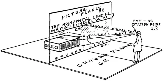
We start with the Picture Plane as it is explained on page 28. This Picture Plane (called P.P. for convenience) stands upright like a transparent wall between the object and the artist. The object and the artist are both standing on a level plane called the Ground Plane (called G.P. for convenience). The Picture Plane is perpendicular to the Ground Plane. The line where they meet is the Ground Line (G.L.).
The artist sees the object through the transparent Picture Plane. Note on the diagram where three points on the object appear on this surface.
Mechanical perspective furnishes a means of locating a sufficient number of these points on the Picture Plane so that the object can be correctly drawn.
We discover that the position of these points can be changed by the artist; by raising or lowering the eye-level and by moving toward or away from the Picture Plane. We also discover that the position of the points can be changed by moving the object.
We determine the height of the artist’s eyes from the Ground Plane, then we draw an eye-level line along the Picture Plane. This is the H.L. or Horizontal Line.
Draw this familiar Eye-Level Line across a sheet of drawing paper, with the parallel Ground Line below it. The paper before us has now become the Picture Plane.
A line from the artist’s eye perpendicular to H.L. is called the Central Visual Ray (C.V.R.).
The point where this ray meets the H.L. is called the Center of Vision (C.V.).
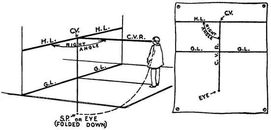
In order to show on our plan drawing the distance between the artist and the Picture Plane (the C.V.R.) we fold the Ground Plane down from the G.L. so that it is flush with the Picture Plane. The line C.V.R. can then be measured straight down from C.V. to Eye or Station Point (S.P.) folded down.
We now have the diagram redrawn in the form of a plan on our sheet of drawing paper showing the artist’s eye-height and his distance from the Picture Plane. We are ready to begin drawing the object.
NOTE
It might be well to explain again that the term Plan as used in this STEP means looking straight down upon the object. No perspective is used in a plan.
An Elevation is a view of the side of an object with no indicated perspective.
(1)
(2)
(3)
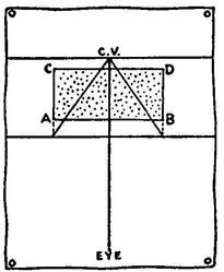
Place the object, a brick for example, in a position opposite the Picture Plane and resting on the Ground Plane. This arrangement is shown in the plan (1).
The corners of the brick are marked A, B, C, and D.
Extend lines AC and BD down to the Ground Line. This gives the true measurement of the line AB on the surface of the Picture Plane.
From these two points (where AC and BD meet the Ground Line) draw lines to the vanishing point C.V. This shows the two sides of the plan AC and BD in perspective. On these lines we must locate the plan of the brick in perspective (A′B′C′D′).
Point C.V. is the vanishing point because it is on the eye-level and also on the Central Visual Ray which is a line from the artist’s eye parallel to the receding sides of the brick. The lines of the brick perpendicular to the Picture Plane recede to this vanishing point.
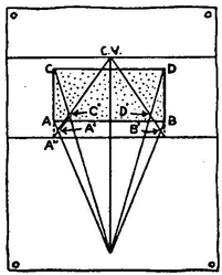
Returning to the plan (2) ; draw lines from A and C to the artist’s eye. These represent the Visual Rays as shown on the diagram on page 193. Where these visual rays cross the receding line (A″ to C.V.) we have two points A′ and C′. The line A′C′ is AC in perspective. The same applies to B′D′.
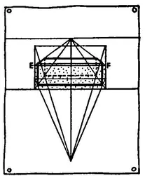
Now draw the elevation of the brick as it rests on the Ground Line (3). Lines from the upper corners E and F can be extended to the vanishing point. This gives the top of the brick in perspective. With the top and the bottom of the brick located we can now determine the sides by drawing lines from A′ B′ C′ and D′ perpendicular to the Ground Line.
The brick does not necessarily have to be centered on the line C.V.R. We can solve the problem by the above method whether the brick is placed to the right or to the left of line C.V.R. providing of course the brick remains parallel with the Ground Line.
Let us try it now in two-point perspective.
So far we have considered a situation in which the face of the brick is parallel to the Picture Plane. Now we turn the brick at an angle and create the same situation as shown on page 50 (the left-hand diagram).
One way of solving angular or two-point perspective is a method used by architects. This method is the combining of the plan, the elevation, and the diagram from page 194.
ARCHITECT’S METHOD
(1)
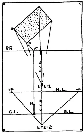
(2)
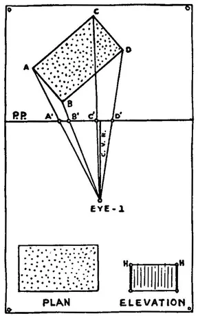
Place the brick back from the Picture Plane (Diagram 1) and show the visual rays from the EYE-1 to the corners of the plan ABCD. These rays pass through the Picture Plane at A′B′C′D′.
Now arrange this as shown in diagram (2). The new Horizontal Line, Ground Line, and Eye position are placed a convenient distance below. EYE-2 is the same distance from H.L. as EYE-1 is from P.P. The C.V.R. Line of the two diagrams becomes a continuous straight line.
We now locate the two vanishing points on line H.L.
Lines from EYE-2 drawn parallel to the two adjacent sides of the brick meet the H.L. at two points. This method is explained on page 50.
We have the plan of the brick; now it is necessary to show its height.
Extend AB until it meets P.P. at A″. From A″ draw a line parallel to C.V.R. and extend it to the Gro...
Table of contents
- DOVER BOOKS ON ART INSTRUCTION AND ANATOMY
- Title Page
- Copyright Page
- Dedication
- FOREWORD
- Table of Contents
- STEP ONE
- STEP TWO
- STEP THREE
- STEP FOUR
- STEP FIVE
- STEP SIX
- STEP SEVEN
- STEP EIGHT
- STEP NINE
- STEP TEN
- STEP ELEVEN
- STEP TWELVE
- STEP THIRTEEN
- STEP FOURTEEN
- STEP FIFTEEN
- STEP SIXTEEN
- STEP SEVENTEEN
- STEP EIGHTEEN
- STEP NINETEEN
- STEP TWENTY
- A CATALOG OF SELECTED DOVER BOOKS IN ALL FIELDS OF INTEREST
Frequently asked questions
Yes, you can cancel anytime from the Subscription tab in your account settings on the Perlego website. Your subscription will stay active until the end of your current billing period. Learn how to cancel your subscription
No, books cannot be downloaded as external files, such as PDFs, for use outside of Perlego. However, you can download books within the Perlego app for offline reading on mobile or tablet. Learn how to download books offline
Perlego offers two plans: Essential and Complete
- Essential is ideal for learners and professionals who enjoy exploring a wide range of subjects. Access the Essential Library with 800,000+ trusted titles and best-sellers across business, personal growth, and the humanities. Includes unlimited reading time and Standard Read Aloud voice.
- Complete: Perfect for advanced learners and researchers needing full, unrestricted access. Unlock 1.5M+ books across hundreds of subjects, including academic and specialized titles. The Complete Plan also includes advanced features like Premium Read Aloud and Research Assistant.
We are an online textbook subscription service, where you can get access to an entire online library for less than the price of a single book per month. With over 1.5 million books across 990+ topics, we’ve got you covered! Learn about our mission
Look out for the read-aloud symbol on your next book to see if you can listen to it. The read-aloud tool reads text aloud for you, highlighting the text as it is being read. You can pause it, speed it up and slow it down. Learn more about Read Aloud
Yes! You can use the Perlego app on both iOS and Android devices to read anytime, anywhere — even offline. Perfect for commutes or when you’re on the go.
Please note we cannot support devices running on iOS 13 and Android 7 or earlier. Learn more about using the app
Please note we cannot support devices running on iOS 13 and Android 7 or earlier. Learn more about using the app
Yes, you can access Perspective Made Easy by Ernest R. Norling in PDF and/or ePUB format, as well as other popular books in Art & Art Techniques. We have over 1.5 million books available in our catalogue for you to explore.