- 256 pages
- English
- ePUB (mobile friendly)
- Available on iOS & Android
eBook - ePub
RF Circuit Design
About this book
It's Back! New chapters, examples, and insights; all infused with the timeless concepts and theories that have helped RF engineers for the past 25 years!RF circuit design is now more important than ever as we find ourselves in an increasingly wireless world. Radio is the backbone of today's wireless industry with protocols such as Bluetooth, Wi-Fi, WiMax, and ZigBee. Most, if not all, mobile devices have an RF component and this book tells the reader how to design and integrate that component in a very practical fashion. This book has been updated to include today's integrated circuit (IC) and system-level design issues as well as keeping its classic "wire lead" material. Design Concepts and Tools Include•The Basics: Wires, Resistors, Capacitors, Inductors•Resonant Circuits: Resonance, Insertion Loss •Filter Design: High-pass, Bandpass, Band-rejection•Impedance Matching: The L Network, Smith Charts, Software Design Tools•Transistors: Materials, Y Parameters, S Parameters•Small Signal RF Amplifier: Transistor Biasing, Y Parameters, S Parameters•RF Power Amplifiers: Automatic Shutdown Circuitry , Broadband Transformers, Practical Winding Hints•RF Front-End: Architectures, Software-Defined Radios, ADC's Effects•RF Design Tools: Languages, Flow, ModelingCheck out this book's companion Web site at: http://www.elsevierdirect.com/companion.jsp?ISBN=9780750685184 for full-color Smith Charts and extra content!
- Completely updated but still contains its classic timeless information
- Two NEW chapters on RF Front-End Design and RF Design Tools
- Not overly math intensive, perfect for the working RF and digital professional that need to build analog-RF-Wireless circuits
Trusted by 375,005 students
Access to over 1.5 million titles for a fair monthly price.
Study more efficiently using our study tools.
Information
Topic
DesignSubtopic
Industrial DesignCHAPTER 1 Components and Systems
Components, those bits and pieces which make up a radio frequency (RF) circuit, seem at times to be taken for granted. A capacitor is, after all, a capacitor—isn’t it? A 1-megohm resistor presents an impedance of at least 1 megohm—doesn’t it? The reactance of an inductor always increases with frequency, right? Well, as we shall see later in this discussion, things aren’t always as they seem. Capacitors at certain frequencies may not be capacitors at all, but may look inductive, while inductors may look like capacitors, and resistors may tend to be a little of both.
In this chapter, we will discuss the properties of resistors, capacitors, and inductors at radio frequencies as they relate to circuit design. But, first, let’s take a look at the most simple component of any system and examine its problems at radio frequencies.
WIRE
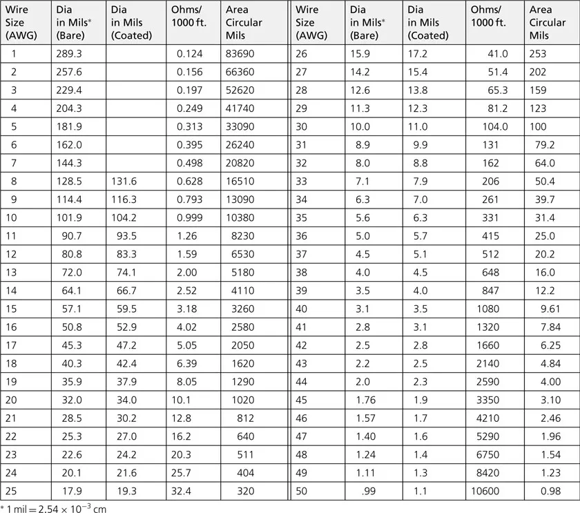
Wire in an RF circuit can take many forms. Wirewound resistors, inductors, and axial- and radial-leaded capacitors all use a wire of some size and length either in their leads, or in the actual body of the component, or both. Wire is also used in many interconnect applications in the lower RF spectrum. The behavior of a wire in the RF spectrum depends to a large extent on the wire’s diameter and length. Table 1-1 lists, in the American Wire Gauge (AWG) system, each gauge of wire, its corresponding diameter, and other characteristics of interest to the RF circuit designer. In the AWG system, the diameter of a wire will roughly double every six wire gauges. Thus, if the last six gauges and their corresponding diameters are memorized from the chart, all other wire diameters can be determined without the aid of a chart (Example 1-1).
TABLE 1-1. AWG Wire Chart
EXAMPLE 1-1
Given that the diameter of AWG 50 wire is 1.0 mil (0.001 inch), what is the diameter of AWG 14 wire?
Solution
AWG 50 = 1 mil
AWG 44 = 2 × 1 mil = 2 mils
AWG 38 = 2 × 2 mils = 4 mils
AWG 32 = 2 × 4 mils = 8 mils
AWG 26 = 2 × 8 mils = 16 mils
AWG 20 = 2 × 16 mils = 32 mils
AWG 14 = 2 × 32 mils = 64 mils (0.064 inch)
Skin Effect
A conductor, at low frequencies, utilizes its entire cross-sectional area as a transport medium for charge carriers. As the frequency is increased, an increased magnetic field at the center of the conductor presents an impedance to the charge carriers, thus decreasing the current density at the center of the conductor and increasing the current density around its perimeter. This increased current density near the edge of the conductor is known as skin effect. It occurs in all conductors including resistor leads, capacitor leads, and inductor leads.
The depth into the conductor at which the charge-carrier current density falls to 1/e, or 37% of its value along the surface, is known as the skin depth and is a function of the frequency and the permeability and conductivity of the medium. Thus, different conductors, such as silver, aluminum, and copper, all have different skin depths.
The net result of skin effect is an effective decrease in the cross-sectional area of the conductor and, therefore, a net increase in the ac resistance of the wire as shown in Fig. 1-1. For copper, the skin depth is approximately 0.85 cm at 60 Hz and 0.007 cm at 1 MHz. Or, to state it another way: 63% of the RF current flowing in a copper wire will flow within a distance of 0.007 cm of the outer edge of the wire.
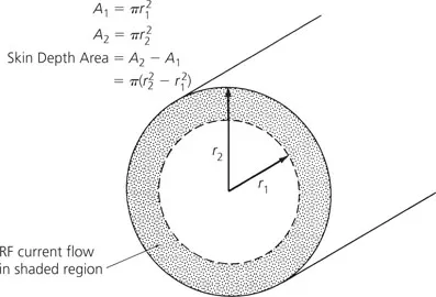
FIG. 1-1. Skin depth area of a conductor.
Straight-Wire Inductors
In the medium surrounding any current-carrying conductor, there exists a magnetic field. If the current in the conductor is an alternating current, this magnetic field is alternately expanding and contracting and, thus, producing a voltage on the wire which opposes any change in current flow. This opposition to change is called self-inductance and we call anything that possesses this quality an inductor. Straight-wire inductance might seem trivial, but as will be seen later in the chapter, the higher we go in frequency, the more important it becomes.
The inductance of a straight wire depends on both its length and its diameter, and is found by:
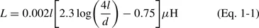
where,
L = the inductance in µH,
l = the length of the wire in cm,
d = the diameter of the wire in cm.
This is shown in calculations of Example 1-2.
EXAMPLE 1-2
Find the inductance of 5 centimeters of No. 22 copper wire.
Solution
From Table 1-1, the diameter of No. 22 copper wire is 25.3 mils. Since 1 mil equals 2.54 × 10⁻³ cm, this equals 0.0643 cm. Substituting into Equation 1-1 gives
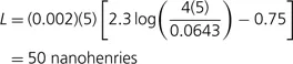
The concept of inductance is important because any and all conductors at radio frequencies (including hookup wire, capacitor leads, etc.) tend to exhibit the property of inductance. Inductors will be discussed in greater detail later in this chapter.
RESISTORS
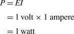
Resistance is the property of a material that determines the rate at which electrical energy is converted into heat energy for a given electric current. By definition:
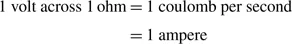
The thermal dissipation in this circumstance is 1 watt.
Resistors are used everywhere in circuits, as transistor bias networks, pads, and signal combiners. However, very rarely is there any thought given to how a resistor actually behaves once we depart from the world of direct current (DC). In some instances, such as in transistor biasing networks, the resistor will still perform its DC circuit function, but it may also disrupt the circu...
Table of contents
- Cover
- Title Page
- Copyright
- Dedication
- Preface
- Acknowledgments
- Table of Contents
- Chapter 1: Components and Systems
- Chapter 2: Resonant Circuits
- Chapter 3: Filter Design
- Chapter 4: Impedance Matching
- Chapter 5: The Transistor at Radio Frequencies
- Chapter 6: Small-Signal RF Amplifier Design
- Chapter 7: RF (Large Signal) Power Amplifiers
- Chapter 8: RF Front-End Design
- Chapter 9: RF Design Tools
- Appendix A: RF and Antennas
- Appendix B: Vector Algebra
- Index
- Instructions for online access
Frequently asked questions
Yes, you can cancel anytime from the Subscription tab in your account settings on the Perlego website. Your subscription will stay active until the end of your current billing period. Learn how to cancel your subscription
No, books cannot be downloaded as external files, such as PDFs, for use outside of Perlego. However, you can download books within the Perlego app for offline reading on mobile or tablet. Learn how to download books offline
Perlego offers two plans: Essential and Complete
- Essential is ideal for learners and professionals who enjoy exploring a wide range of subjects. Access the Essential Library with 800,000+ trusted titles and best-sellers across business, personal growth, and the humanities. Includes unlimited reading time and Standard Read Aloud voice.
- Complete: Perfect for advanced learners and researchers needing full, unrestricted access. Unlock 1.5M+ books across hundreds of subjects, including academic and specialized titles. The Complete Plan also includes advanced features like Premium Read Aloud and Research Assistant.
We are an online textbook subscription service, where you can get access to an entire online library for less than the price of a single book per month. With over 1.5 million books across 990+ topics, we’ve got you covered! Learn about our mission
Look out for the read-aloud symbol on your next book to see if you can listen to it. The read-aloud tool reads text aloud for you, highlighting the text as it is being read. You can pause it, speed it up and slow it down. Learn more about Read Aloud
Yes! You can use the Perlego app on both iOS and Android devices to read anytime, anywhere — even offline. Perfect for commutes or when you’re on the go.
Please note we cannot support devices running on iOS 13 and Android 7 or earlier. Learn more about using the app
Please note we cannot support devices running on iOS 13 and Android 7 or earlier. Learn more about using the app
Yes, you can access RF Circuit Design by Christopher Bowick in PDF and/or ePUB format, as well as other popular books in Design & Industrial Design. We have over 1.5 million books available in our catalogue for you to explore.