1.1 Grounding
When to consider grounding
1.1.1 Grounding within one unit
1.1.2 Chassis ground
1.1.3 The conductivity of aluminum
Other materials
1.1.4 Ground loops
1.1.5 Power supply returns
Varying loads
Power rail feed
Conductor impedance
1.1.6 Input signal ground
Connection to O V elsewhere on the PCB
Connection to O V within the unit
External ground connection
1.1.7 Output signal ground
Avoiding the common impedance
1.1.8 Inter-board interface signals
Partitioning the signal return
1.1.9 Star-point grounding
1.1.10 Ground connections between units
Breaking the ground link
1.1.11 Shielding
Which end to ground for LF shielding
Electrostatic screening
Surface transfer impedance
1.1.12 The safety earth
1.2 Wiring and cables
1.2.1 Wire types
Wire inductance
Equipment wire
Wire-wrap wire
1.2.2 Cable types
1.2.3 Power cables
1.2.4 Data and multicore cables
Data communication cables
Structured data cable
Shielding and microphony
1.2.5 RF cables
1.2.6 Twisted pair
1.2.7 Crosstalk
Digital crosstalk
1.3 Transmission lines
Transmission line effects
Critical lengths for pulses
1.3.1 Characteristic impedance
1.3.2 Time domain
Forward and reflected waves
Ringing
The Bergeron diagram
The uses of mismatching
1.3.3 Frequency domain
Standing wave distribution versus frequency
Impedance transformation
Lossy lines
Understanding the transmission line impedance graphically
1.1 Grounding
A fundamental property of any electronic or electrical circuit is that the voltages present within it are referenced to a common point, conventionally called the ground. This term is derived from electrical engineering practice, when the reference point is often taken to a copper spike literally driven into the ground. This point may also be a connection point for the power to the circuit, and it is then called the 0 V (nought-volt) rail, and ground and 0 V are frequently (and confusingly) synonymous. Then, when we talk about a five-volt supply or a minus-twelve-volt supply or a two-and-a-half-volt reference, each of these are referred to the 0 V rail.
At the same time, ground is not the same as 0 V. A ground wire connects equipment to earth for safety reasons, and does not carry a current in normal operation. However, in this chapter the word “grounding” will be used in its usual sense, to include both safety earths and signal and power return paths.
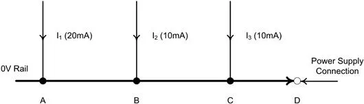
Perhaps the greatest single cause of problems in electronic circuits is that 0 V and ground are taken for granted. The fact is that in a working circuit there can only ever be one point which is truly at 0 V; the concept of a “0 V rail” is in fact a contradiction in terms. This is because any practical conductor has a finite non-zero resistance and inductance, and Ohm’s law tells us that a current flowing through anything other than a zero impedance will develop a voltage across it. A working circuit will have current flowing through those conductors that are designated as the 0 V rail and therefore, if any one point of the rail is actually at 0 V (say, the power supply connection) the rest of the rail will not be at 0 V. This can be illustrated with the example in Figure 1.1.
FIGURE 1.1 Voltages along the 0 V rail
Assume the 0 V conductor has a resistance of 10 mΩ/inch and that points A, B, C and D are each one inch apart. The voltages at points A, B and C referred to D are:
Now, after such a trenchant introduction, you might be tempted to say well, there are millions of electronic circuits in existence, they must all have 0 V rails, they seem to work well enough, so what’s the problem? Most of the time there is no problem. The impedance of the 0 V conductor is in the region of milliohms, the current levels are milliamps, and the resulting few hundred microvolts drop doesn’t offend the circuit at all; 0 V plus 500 μV is close enough to 0 V for nobody to worry.
The difficulty with this answer is that it is then easy to forget about the 0 V rail and assume that it is 0 V under all conditions, and subsequently be surprised when a circuit oscillates or otherwise doesn’t work. Those conditions where trouble is likely to arise are:
• where current flows are measured in amps rather than milli- or microamps;
• where the 0 V conductor impedance is measured in ohms rather than milliohms;
• where the resultant voltage drop, whatever its value, is of a magnitude or in such a configuration as to affect the circuit operation.
When to consider grounding
One of the attributes of a good circuit designer is to know when these conditions need to be carefully considered and when they may be safely ignored. A frequent complication is that you as circuit designer may not be responsible for the circuit’s layout, which is handed over to a layout draughtsman (who may in turn delegate many routing decisions to a software package). Grounding is always sensitive to layout, whether of discrete wiring or of printed circuits, and the designer must have some knowledge of and control over this if the design is not to be compromised.
The trick is always to be sure that you know where ground return currents are flowing, and what their consequences will be; or, if this is too complicated, to make sure that wherever they flow, the consequences will be minimal. Although the above comments are aimed at 0 V and ground connections, because they are the ones most taken for granted, the nature of the problem is universal and applies to any conductor through which current flows. The power supply rail (or rails) is another special case where conductor impedance can create difficulties.
1.1.1 Grounding within one unit
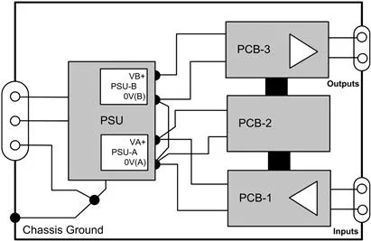
In this context, “unit” can refer to a single circuit board or a group of boards and other wiring connected together within an enclosure such that you can identify a “local” ground point, for instance the point of entry of the mains earth. An example might be as shown in Figure 1.2. Let us say that printed circuit board (PCB) 1 contains input signal conditioning circuitry, PCB2 contains a microprocessor for signal processing and PCB3 contains high-current output drivers, such as for relays and for lamps. You may not place all these functions on separate boards, but the principles are easier to outline and understand if they are considered separately. The power supply unit (PSU) provides a low-voltage supply for the first two boards, and a higher-power supply for the output board. This is a fairly common system layout and Figure 1.2 will serve as a starting point to illustrate good and bad practice.
FIGURE 1.2 Typical intra-unit wiring scheme
1.1.2 Chassis ground
First of all, note that connections are only made to the metal chassis or enclosure at one point. All wires that need to come to the chassis are brought to this point, which should be a metal stud dedicated to the purpose. Such connections are the mains safety earth (about which more later), the 0 V power rail, and any possible screening and filtering connections that may be required in the power supply itself, such as an electrostatic screen in t...