Technology & Engineering
Valves
Valves are mechanical devices used to control the flow of fluids within a system. They can be found in various applications, such as plumbing, heating, and industrial processes. Valves work by opening, closing, or partially obstructing the passage of the fluid, allowing for precise regulation and control of flow rates and pressures.
Written by Perlego with AI-assistance
Related key terms
1 of 5
8 Key excerpts on "Valves"
 eBook - PDF
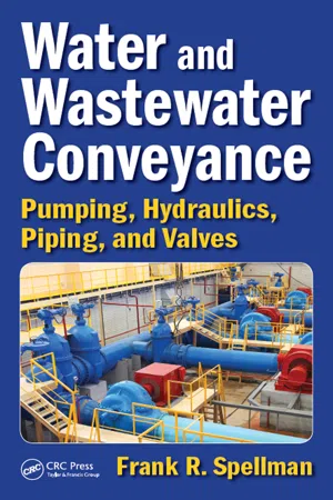
Water and Wastewater Conveyance
Pumping, Hydraulics, Piping, and Valves
- Frank R. Spellman(Author)
- 2016(Publication Date)
- CRC Press(Publisher)
Section V Valves 333 18 Flow Control Devices Any water or wastewater operation will have many Valves that require attention. A maintenance operator must be able to identify and locate different Valves to inspect them, adjust them, or repair or replace them. For this reason, the operator should be familiar with all Valves, especially those that are vital parts of a piping system. DEFINITION AND FUNCTION OF Valves A valve is defined as any device by which the flow of fluid may be started, stopped, or regulated by a movable part that opens or obstructs passage. As applied in fluid power systems, Valves are used for controlling the flow, the pressure, and the direc-tion of the fluid flow through a piping system. The fluid may be a liquid, a gas, or some loose material in bulk (such as a biosolids slurry). Designs of Valves vary, but all Valves have two features in common: a passageway through which fluid can flow and some kind of movable (usually machined) part that opens and closes the passageway. Note: It is all but impossible, obviously, to operate a practical fluid power sys-tem without some means of controlling the volume and pressure of the fluid and directing the flow of fluid to the operating units. This is accomplished by the incor-poration of various types of Valves. Whatever type of valve is used in a system, it must be accurate in the control of fluid flow and pressure and the sequence of operation. Leakage between the valve element and the valve seat is reduced to a negligible quantity by precision-machined surfaces, resulting in carefully controlled clearances. This is, of course, one of the very important reasons for minimizing contamination in fluid power systems. Contamination can make Valves stick, plug up small orifices, and cause abrasions of the valve seating surfaces, resulting in leakage between the valve element and valve seat when the valve is in the closed position.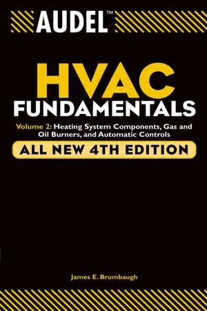 eBook - PDF
Audel HVAC Fundamentals, Volume 2
Heating System Components, Gas and Oil Burners, and Automatic Controls
- James E. Brumbaugh(Author)
- 2004(Publication Date)
- Audel(Publisher)
Chapter 9 Valves and Valve Installation A valve is a device used for controlling the flow or pressure of a fluid in the pipes of steam and hot-water heating systems. Valves are generally restricted in use to the control function for which they were designed. Specifically, a valve may be used to control a fluid in one of the following ways: • Stopping its flow • Checking its flow • Throttling its flow • Diverting its flow • Reducing its temperature • Relieving its pressure • Reducing or regulating its pressure Valve Components and Terminology The operation of a valve may be controlled either internally or externally, depending on the type of valve. For example, the opera-tion of a check valve depends on the fluid flow in the pipe. Because the operation of this type of valve is controlled internally and is therefore automatic in nature, no means are provided for external adjustment. Access to the working parts (disc, seat rings, ball, and so on) of a check valve is usually obtained through a cap secured to the valve bolt by bolts or a threaded connection. The operation of most other types of Valves is controlled externally, either manually or automatically. Generally speaking, an externally controlled valve consists of a body to which an extension (a bonnet, yoke, or yoke and bonnet) is attached. The bonnet contains the valve stem, packing nut, and stuffing box. The yoke consists of upright arms mounted on the bonnet or on a gasket placed on the neck of the valve body. When a yoke is used, the stem is threaded and guided through the upper yoke arm. The valve stem is an adjustable screw or shaft inside the bonnet that opens or closes the valve by moving a disc holder and disc attached to the end of the stem up or down inside the valve body 445 446 Chapter 9 (see Figure 9-1). The valve closes when the disc makes full contact with the valve seat, a stationary surface in the valve body. The valve opens when the stem pulls the disc holder and disc up off the valve seat.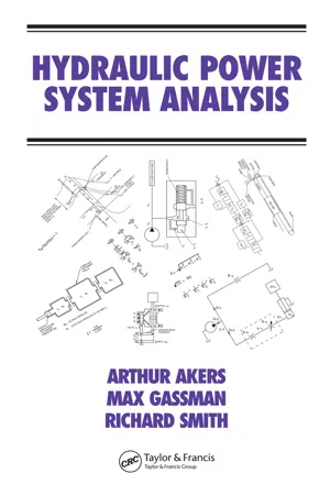 eBook - PDF
- Arthur Akers, Max Gassman, Richard Smith(Authors)
- 2006(Publication Date)
- CRC Press(Publisher)
7 Valves AND THEIR USES 7.1 INTRODUCTION All fluid power circuits incorporate Valves. Many authors, e.g., [1], state that there are three categories of Valves. These are directional control, pressure control, and flow control. A simple application of a directional control valve would be the valve controlled manually by an operator that determines which end of a cylinder is connected to a pump. The most com-monly encountered pressure control valve is the pressure relief valve used to protect components from excess forces caused by overloads or actuators reaching the end of their travel. A flow control valve is used to route oil to a secondary circuit in such a fashion that flow rate remains approximately constant even when pressure is varying. The principle of operation of most Valves is the same. A valve is a variable area orifice where the orifice area may be controlled by conditions in a circuit, for example a pressure relief valve operates without operator intervention. Alternatively the orifice area may be controlled by an operator as in a directional control valve. This categorization is a little simplistic because not all directional control Valves are directly linked to an operator. Valves may be moved by electrical actuators and by pressure actuators. Thus many Valves are quite complicated in terms of the number of parts in the valve. The valve operation is dynamic and often must be analyzed using methods outlined later in the text (Chapters 11 or 13). Valves may also have feedback loops within them and the stability may have to be examined using control theory. At the risk of being repetitive, we should briefly revisit the energy equa-tion Equation 3.5. In most Valves, fluid at high pressure passes through a pressure drop caused by the orifice. Valves are an indispensable part of 163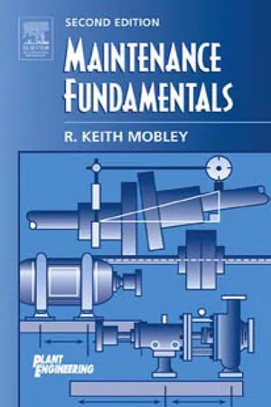 eBook - PDF
- R. Keith Mobley(Author)
- 2011(Publication Date)
- Butterworth-Heinemann(Publisher)
13 CONTROL Valves Control Valves can be grouped into two major classifications: process and fluid power. Process Valves control the flow of gases and liquids through a process system. Fluid-power Valves control pneumatic or hydraulic systems. P ROCESS Process-control Valves are available in a variety of sizes, configurations, and materials of construction. Generally, this type of valve is classified by its internal configuration. Configuration The device used to control flow through a valve varies with its intended function. The more common types are ball, gate, butterfly, and globe Valves. Ball Ball Valves (Figure 13.1) are simple shut-off devices that use a ball to stop and start the flow of fluid downstream of the valve. As the valve stem turns to the open position, the ball rotates to a point where part or the entire hole machined through the ball is in line with the valve-body inlet and outlet. This allows fluid to pass through the valve. When the ball rotates so that the hole is perpendicular to the flow path, the flow stops. Most ball Valves are quick-acting and require a 90-degree turn of the actuator lever to fully open or close the valve. This feature, coupled with the turbulent 266 flow generated when the ball opening is only partially open, limits the use of the ball valve. Use should be limited to strictly an ‘‘on-off ’’ control function (i.e., fully open or fully closed) because of the turbulent-flow condition and severe friction loss when in the partially open position. They should not be used for throttling or flow-control applications. Ball Valves used in process applications may incorporate a variety of actuators to provide direct or remote control of the valve. The more common actuators are either manual or motor-operated. Manual values have a hand wheel or lever attached directly or through a gearbox to the valve stem. The valve is opened or closed by moving the valve stem through a 90-degree arc. eBook - PDF
Applied Engineering Technology NQF4 SB
TVET FIRST
- Sparrow Consulting(Author)
- 2013(Publication Date)
- Macmillan(Publisher)
Hydraulic Valves are Valves used to regulate the flow of liquids. The taps in your house are examples of hydraulic Valves. Pneumatic Valves are Valves that regulate the flow of gases. The knob on your gas stove is an example of a pneumatic valve. Relief Valves Figure 2.23 Relief Valves release excess pressure from a system Relief Valves do exactly what their name implies. They are used to relieve pressure from a system. It may happen that the pressure in a pipe becomes too high. When this happens, the relief valve opens and lets some of the liquid or oil out to release the pressure. The valve shuts itself again when the pressure drops. The valve in Figure 2.23 acts like this. When the pressure inside the system increases, the valve disc at the inlet of the valve is pushed upward. When this upward pressure is bigger than the pressure applied by the spring, the valve will lift. Some of the liquid or gas is then released through the outlet valve: a device used to control the flow of liquids or gases regulate: control hydraulic: working with water pneumatic: working with air Words & Terms relief valve: valve used to reduce pressure in a system Words & Terms Lever Shaft Yoke Cap Gag screw Upper spring step Lower spring step Retaining ring Spring Body Disc Stem Compression screw 37 Module 2: The operating principles of mechanical components used in the engineering-related design industries on the side. When the pressure drops to a level lower than the spring pressure, the spring lets the disc down again, closing the valve. In Figure 2.24 you will see that fluid flowing upward because of excess pressure forces the ball off its seat . The ball then presses the spring down, letting excess fluid flow out. In this way the system is protected from overloading. The amount of pressure that the spring can take is set by turning the adjustment knob . In this way the maximum overload pressure is increased or decreased. No longer available |Learn more
- Jean Riescher Westcott, A.K. Gupta, S.K. Arora(Authors)
- 2023(Publication Date)
- Mercury Learning and Information(Publisher)
CHAPTER 7CONTROL Valves
INTRODUCTION
In a pneumatic or hydraulic system, the objective is generally to supply power from a compressor or pump to the fluid actuator (i.e. , motor or cylinder). But the problem is not always the same, example, sometimes the stroke of the cylinder moves very fast whereas sometimes it is extends very slowly. The solution to these fluid problems can be obtained by using a combination of Valves.In almost every fluid system, Valves are required to control the direction, flow, pressure, or quantity of fluid. Based on the application, Valves can be divided into four categories: direction control Valves, flow control Valves, pressure control Valves, and special Valves . Valves can be classified according to their construction, i.e. , poppet Valves and spool Valves . We can also classify the Valves on the basis of mode of actuation, i.e. , they can be actuated manually, electrically, electromagnetically, or with the help of fluids. This chapter concentrates on explaining identification, function, construction, and location of Valves in relation to hydraulic and pneumatic circuits.Hydraulic systems are high-pressure systems and pneumatic systems are low-pressure systems. Hydraulic Valves are made of strong materials (e.g., steel) and are precision manufactured. Pneumatic Valves are made from cheaper materials (e.g., aluminum and polymer) and are cheaper to manufacture.CLASSIFICATION OF Valves
Valves are classified as:Direction control valveFlow control valvePressure control valveCheck valveDirection control Valves are most important among all other Valves because of their frequent use in a fluid power system. As the name implies, they are used to direct the flow of fluid in a desired direction.Flow control Valves are those in which the flow of fluid is varied according to requirements. They are of fixed and adjustable flow control type.Pressure control Valves
- Barbara Renner(Author)
- 2017(Publication Date)
- Routledge(Publisher)
CHAPTER 2 Control Valves2.01 Of all of the different types and styles of equipment manufactured for the water/wastewater industry, Valves are made in the greatest variety of shapes, styles, and designs. They are also available with the greatest number of different kinds of actuating devices.2.02 Most operating and maintenance personnel know how many of the basic styles of smaller Valves (gate, ball, globe, and check) are constructed and how they should be maintained. They, therefore, will not be covered in this chapter. Instead, the chapter will discuss the larger Valves that regulate and control the flow of fluid through the plant, in the distribution system, and for fluid transfer (force main) systems.2.03 To simplify the presentation of the different Valves, the text will first discuss the construction and operating principles of the various valve styles (ball, gate, globe, etc.). The second portion of the text will discuss how the different styles are used (flow control, pressure control, etc.) and the various methods by which they are controlled. A third section will discuss different kinds of valve actuating devices, while the last section will cover some valve maintenance requirements.2.04 It should be pointed out that any given style of valve from any manufacturer may be used for more than one purpose. For example, a globe valve may be used for a number of flow or pressure control applications. The types of controlling devices and maybe some changes to the internal components determines the valve descriptive name (pressure reducing, pressure regulating, pressure relief, etc.). Although, this may seem a little confusing, the text will explain the differences.2.05 The importance and value of a valve maintenance program should not be underestimated. Valves are often ignored because they are not accessible or do not cause any
- George E. Totten, Victor J. De Negri(Authors)
- 2011(Publication Date)
- CRC Press(Publisher)
38 1.4.4.2 Normally Open Pressure Control Valves (Pressure-Reducing Valves) ....... 40 1.4.5 Flow Control Valves ................................................................................................... 41 1.4.6 Directional Continuous Control Valves ...................................................................... 43 1.4.6.1 Servo-Valves ................................................................................................. 43 1.4.6.2 Proportional Directional Control Valves ..................................................... 44 1.4.6.3 Fundamental Model and Characteristic Curves .......................................... 45 1.4.7 Hydraulic Accumulators ............................................................................................. 47 1.4.8 Reservoir and Its Accessories ..................................................................................... 48 1.4.9 Filters .......................................................................................................................... 49 1.4.10 Hydraulic Fluid ........................................................................................................... 51 Acknowledgments ............................................................................................................................ 51 References ........................................................................................................................................ 51 2 Handbook of Hydraulic Fluid Technology, Second Edition 1.1 INTRODUCTION A hydraulic system, from a general perspective, is an arrangement of interconnected components that uses a liquid under pressure to provide energy transmission and control. It has an extremely broad range of applications covering basically all fields of production, manufacturing and service. Consequently, the energy transmission and control requirements are very diverse and thus the struc-ture of each hydraulic system has its specificities.
Index pages curate the most relevant extracts from our library of academic textbooks. They’ve been created using an in-house natural language model (NLM), each adding context and meaning to key research topics.