
- 448 pages
- English
- ePUB (mobile friendly)
- Available on iOS & Android
eBook - ePub
Electronic Navigation Systems
About this book
Maritime navigation has rapidly developed since the publication of the last edition of the title with methods of global position fixing for shipping becoming standardized. As in the previous two editions, this edition will provide a sound basis for the understanding of modern navigation systems and brings the student or professional up-to-date with the latest developments in technology and the growing standardization of maritime navigation techniques.
Developed with close scrutiny from the US Merchant Marine Academy and the major maritime navigation centres in the UK, out-dated techniques have been replaced by an expanded section on the now standard Navstar GPS systems and the Integrated Nav. In addition, a new chapter on the application of electronic charts will also be included, as well as problems at the end of each chapter with worked solutions.
Trusted by 375,005 students
Access to over 1.5 million titles for a fair monthly price.
Study more efficiently using our study tools.
Information
Chapter 1
Radio wave propagation and the frequency spectrum
1.1 Introduction
This chapter outlines the basic principles of signal propagation and the radio frequency spectrum used by the navigation systems likely to be encountered on board merchant ships. The use of radio waves for terrestrial global communications and navigation causes major problems, particularly in the areas of frequency allocation and interference. Consequently, for safe and efficient working practices to be maintained on the restricted radio frequency spectrum, it is essential that this limited resource is carefully policed.
Radio waves cannot and do not respect international boundaries and, consequently, disputes arise between nations over the use of radio frequencies. The international governing body for radio communications services is the International Telecommunications Union (ITU) which, quite rightly, strictly regulates the allocation and use of frequencies. Any dispute that arises is settled by the ITU through various committees and affiliated organizations. All users of radiocommunications systems must be aware that they are licensed to use only specific frequencies and systems in order to achieve information transfer. It would be chaos if this were not so. Essential services, aeronautical, maritime or land based, would not be able to operate otherwise and lives could well be put at risk.
1.2 Maritime navigation systems and their frequencies
Maritime radio navigation requirements have always posed unique problems for the shipboard operator. A ship at sea presents many difficulties to the radio communications design engineer. The ship is constructed of steel which, when floating in salt water, becomes a very effective electromagnetic screen capable of rejecting or reflecting radio waves. In addition, modern oceangoing vessels are streamlined, spelling an end to those sturdy structures, i.e. smoke stacks and masts, that traditionally were used for holding antenna systems. Consequently, shipboard antenna systems tend to be less efficient than was once the case, giving rise to difficulties in both transmission and reception.
Maritime radio navigation and communication systems operate in a number of frequency bands. Listed below is a brief summary.
• Loran-C on the medium frequency 100 kHz.
• Navtex data on 518 kHz.
• Voice, radiotelex and digital selective calling in medium frequency band 1.6–3.4 MHz.
• Voice, radiotelex and DSC in high frequency bands between 3 and 30 MHz
• Voice and DSC in the very high frequency band 30–300 MHz.
• RADAR and SART on the frequency of 9 GHz.
• GPS satellite signals on L-band frequencies.
• INMARSAT communications signals on L-band frequencies.
In each case, the carrier frequency used has been chosen to satisfy two main criteria, those of geographical range and the ability to carry the relevant information. The geographical range of a radio wave is affected by many parameters, but in the context of this book, range may basically be related to the choice of frequency band, which in turn determines the method of radio wave propagation.
1.3 Radio wave radiation
The propagation of radio waves is a highly complex natural phenomenon. It is simplified in the following pages to provide an understanding of the subject with a level of knowledge necessary to comprehend modern navigation systems.
Energy is contained in a transmitted radio wave in two forms, electrostatic energy and electromagnetic energy. The radiation of energy from a simple antenna may be described by considering a centre-fed dipole antenna, which is shown electrically in Figure 1.1.
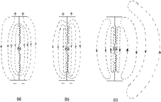
Figure 1.1 Radio wave radiation from a centre-fed dipole antenna.
The antenna shown is formed of two coils, each end of which is at the opposite potential to the other with reference to the centre point. As a complete unit, the antenna forms a tuned circuit that is critically resonant at the carrier frequency to be radiated. The two plates, one at each end of the coil assembly, form a capacitor. Radio frequency current, from the output stage of a suitable transmitter, shown here as a generator, is applied at the centre of the two coils. One of the basic electrical laws of physics states that whenever an electron has its velocity altered by an accelerating force there will be a detachment of energy. In the case of an antenna system this detachment is the energy that is lost from the transmitter and radiated as electrical energy into the atmosphere.
The diagrams clearly show the distribution of the electric field produced around an antenna when an oscillatory radio frequency is applied to it. In Figure 1.1(a) the top plate of the antenna is instantaneously driven positive with respect to the base plate and the current flow in the wire is zero. At this instant the field produced is entirely electric and the electrostatic lines of force are as shown in the diagram.
After the peak of the signal has passed, electrons will begin to flow upwards to produce a current flow in the wire. The electric field will now start to collapse (Figure 1.1(b)) and the ends of the lines of force come together to form loops of electrostatic energy. After the potential difference (positive top plate to negative base plate) across the two plates of the effective capacitor has fallen to zero, current continues to flow and, in so doing, starts to charge the effective capacitor plates in the opposite direction. This charge forms new lines of force in the reverse direction to the previous field, negative to the top plate and positive at its base. The collapse of the initial electrostatic field lags the change in potential that caused it to occur and, consequently, the new electric field starts to expand before the old field has completely disappeared. The electric fields thus created (Figure 1.1(c)) will be caused to form loops of energy, with each new loop forcing the previous loop outwards, away from the antenna. Thus, radio frequency energy is radiated as closed loops of electrostatic energy.
Because a minute current is flowing around each complete loop of energy, a magnetic field will be created around the loop at 90° to it. Thus, the magnetic lines of force produced around the vertical electric field created by a vertical antenna, will be horizontal. Two fields of energy, in space quadrature, have thus been created and will continue in their relative planes as the radio wave moves away from the transmitting antenna.
The electric and magnetic inductive fields are in both time and space quadrature and are 90°out of phase with each other in time, and at right angles to each other in space. The electric field is of greatest importance to the understanding of radio wave propagation, the magnetic field only being present when current flows around the loop as the electric field changes.
Figure 1.2 shows the relative directions of the electric field (E), the magnetic field (H) and the direction of propagation. The oscillating electric field is represented by the vertical vector OE, the magnetic field by OH, and the direction of propagation by OD. Another electrical law of physics, Fleming's right-hand rule, normally applied to the theory of electrical machines, applies equally to the direction of propagation of the radio wave.
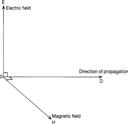
Figure 1.2 The angular relationship of the E and H fields.
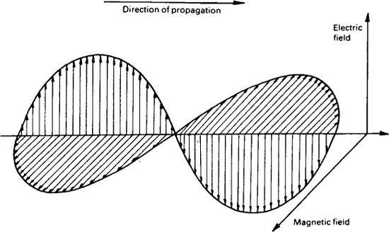
Figure 1.3 Amplitude variations of the E and H fields.
At any instantaneous point along the sinusoidal wave of the electric field it is possible to measure a minute current flow in the loop of energy. The current will be increasing and decreasing as it follows the rate of change of amplitude of the sinusoidal frequency (carrier wave) of the radio wave (see Figure 1.3). It is this instantaneous change of current which, when in contact with a receiving antenna, causes a current to flow at the receiver input and a minute signal voltage, called an electromotive force (e.m.f.), to appear across the antenna input.
The transmitted signal may now be considered to be a succession of concentric loops of ever-increasing radius, each one a wave...
Table of contents
- Cover Page
- Half Title Page
- Title Page
- Copyright Page
- Contents
- Preface
- Acknowledgements
- Chapter 1 Radio wave propagation and the frequency spectrum
- Chapter 2 Depth sounding systems
- Chapter 3 Speed measurement
- Chapter 4 Loran-C
- Chapter 5 Satellite navigation
- Chapter 6 Integrated bridge systems
- Chapter 7 Electronic charts
- Chapter 8 The ship's master compass
- Chapter 9 Automatic steering
- Chapter 10 Radio direction finding
- Chapter 11 Global Maritime Distress and Safety System
- appendix1 Computer functions
- appendix2 Glossary of microprocessor and digital terms
- appendix3 Serial communication
- appendix4 United States Coast Guard Navigation Center (NAVCEN)
- Index
Frequently asked questions
Yes, you can cancel anytime from the Subscription tab in your account settings on the Perlego website. Your subscription will stay active until the end of your current billing period. Learn how to cancel your subscription
No, books cannot be downloaded as external files, such as PDFs, for use outside of Perlego. However, you can download books within the Perlego app for offline reading on mobile or tablet. Learn how to download books offline
Perlego offers two plans: Essential and Complete
- Essential is ideal for learners and professionals who enjoy exploring a wide range of subjects. Access the Essential Library with 800,000+ trusted titles and best-sellers across business, personal growth, and the humanities. Includes unlimited reading time and Standard Read Aloud voice.
- Complete: Perfect for advanced learners and researchers needing full, unrestricted access. Unlock 1.5M+ books across hundreds of subjects, including academic and specialized titles. The Complete Plan also includes advanced features like Premium Read Aloud and Research Assistant.
We are an online textbook subscription service, where you can get access to an entire online library for less than the price of a single book per month. With over 1.5 million books across 990+ topics, we’ve got you covered! Learn about our mission
Look out for the read-aloud symbol on your next book to see if you can listen to it. The read-aloud tool reads text aloud for you, highlighting the text as it is being read. You can pause it, speed it up and slow it down. Learn more about Read Aloud
Yes! You can use the Perlego app on both iOS and Android devices to read anytime, anywhere — even offline. Perfect for commutes or when you’re on the go.
Please note we cannot support devices running on iOS 13 and Android 7 or earlier. Learn more about using the app
Please note we cannot support devices running on iOS 13 and Android 7 or earlier. Learn more about using the app
Yes, you can access Electronic Navigation Systems by Laurie Tetley,David Calcutt in PDF and/or ePUB format, as well as other popular books in Technology & Engineering & Human Geography. We have over 1.5 million books available in our catalogue for you to explore.