
eBook - ePub
Arduino meets MATLAB: Interfacing, Programs and Simulink
Anita Gehlot, Rajesh Singh, Bhupendra Singh
This is a test
Compartir libro
- English
- ePUB (apto para móviles)
- Disponible en iOS y Android
eBook - ePub
Arduino meets MATLAB: Interfacing, Programs and Simulink
Anita Gehlot, Rajesh Singh, Bhupendra Singh
Detalles del libro
Vista previa del libro
Índice
Citas
Información del libro
This book provides a single platform for beginners in systems engineering to start Arduino interface projects with MATLAB®. It covers the basics of the programming with Arduino and Arduino interfacing with MATLAB® with and without the use or I/O packages.
Preguntas frecuentes
¿Cómo cancelo mi suscripción?
¿Cómo descargo los libros?
Por el momento, todos nuestros libros ePub adaptables a dispositivos móviles se pueden descargar a través de la aplicación. La mayor parte de nuestros PDF también se puede descargar y ya estamos trabajando para que el resto también sea descargable. Obtén más información aquí.
¿En qué se diferencian los planes de precios?
Ambos planes te permiten acceder por completo a la biblioteca y a todas las funciones de Perlego. Las únicas diferencias son el precio y el período de suscripción: con el plan anual ahorrarás en torno a un 30 % en comparación con 12 meses de un plan mensual.
¿Qué es Perlego?
Somos un servicio de suscripción de libros de texto en línea que te permite acceder a toda una biblioteca en línea por menos de lo que cuesta un libro al mes. Con más de un millón de libros sobre más de 1000 categorías, ¡tenemos todo lo que necesitas! Obtén más información aquí.
¿Perlego ofrece la función de texto a voz?
Busca el símbolo de lectura en voz alta en tu próximo libro para ver si puedes escucharlo. La herramienta de lectura en voz alta lee el texto en voz alta por ti, resaltando el texto a medida que se lee. Puedes pausarla, acelerarla y ralentizarla. Obtén más información aquí.
¿Es Arduino meets MATLAB: Interfacing, Programs and Simulink un PDF/ePUB en línea?
Sí, puedes acceder a Arduino meets MATLAB: Interfacing, Programs and Simulink de Anita Gehlot, Rajesh Singh, Bhupendra Singh en formato PDF o ePUB, así como a otros libros populares de Informatik y Programmierung. Tenemos más de un millón de libros disponibles en nuestro catálogo para que explores.
Información
Categoría
InformatikCategoría
ProgrammierungArduino Interfacing with Actuators
Rajesh Singh, Anita Gehlot, Bhupendra Singh, Sushabhan Choudhury
Abstract
An actuator is a component which is responsible for moving or controlling a mechanism. An actuator requires a control signal and a source of energy. This chapter explains the working of actuator with the help of different methods.
Keywords: AC motor, Arduino, DC motor, L293D, Stepper motor, Servo motor.
5.1. DC motor control with transistor ‘H’ bridge
A DC motor is a device that converts electrical energy into mechanical energy. It has vital importance for the industry. Fig. (5.1) shows the block diagram of the system, comprises of Arduino, power supply, DC motor, LED. It is designed to control the DC motor with ‘H’ bridge (2N2222), LEDs are connected to check the change in the status of inputs to motor in order to make it move in forward and reverse direction. To make H bridge four 2N2222 transistors are used- Q1, Q2, Q3, Q4.
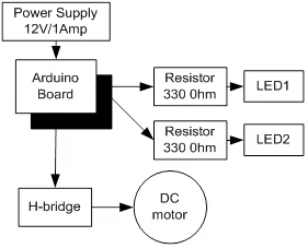
Block diagram for the interfacing of DC motor.
5.1.1. Circuit Diagram
Connect all the components to Arduino as per the connections as described-
- Make collector of Q1 & Q2 common and connect to positive terminal of +12V DC.
- Make emitter of Q3 & Q4 common and connect to negative terminal of +12V DC and ‘GND’.
- Make base of Q1 & Q4 common and connect to pin9 of Arduino.
- Make base of Q2 & Q3 common and connect to pin10 of Arduino.
- LEDs are also connected parallel to inputs of H -bridge.
- +12V DC jack of power supply is connected to DC jack of Arduino Uno.
Fig. (5.2) shows circuit diagram for the interfacing of DC motor.
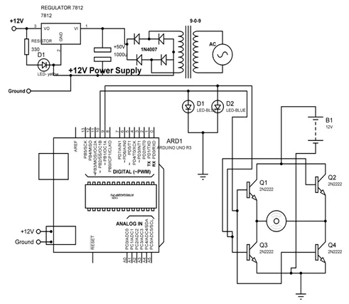
Circuit diagram for the interfacing of DC motor.
5.1.2. Program
int MPIN1 = 10;
int MPIN2 = 9;
void setup()
{
// initialize pin10 and 9 as output
pinMode(MPIN1, OUTPUT);
pinMode(MPIN2, OUTPUT);
}
void loop()
{
digitalWrite(MPIN1, HIGH); // make 10 and 9 pin HIGH and LOW respectively
digitalWrite(MPIN2, LOW);
delay(1000); // wait for a 1000 millisecond
digitalWrite(MPIN1, LOW); // make 9 and 10 pin HIGH and LOW respectively
digitalWrite(MPIN2, HIGH);
delay(1000); // wait for a 1000 millisecond
}
5.1.3. Proteus Simulation Model
Connect the components with Arduino as described in section 5.1.1 in the virtual environment of Proteus simulator. Power supply need not to be connected in the virtual environment of Proteus. Load the program as described in section 5.1.2 and check the feasibility and working of the circuit. Fig. (5.3) shows the Proteus model for the system.
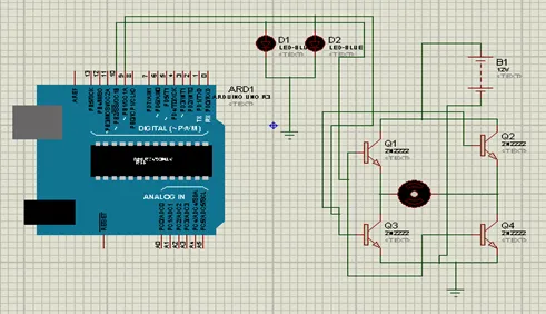
Proteus simulation model for the Arduino interfacing with DC motor.
5.2. DC motor control with L293D
L293D is 14 pin motor driver IC. DC motor upto 12V/1A ca be controlled with this.Fig. (5.4) shows the block diagram of the system, comprises of Arduino, power supply, DC motor, L293D, LED. It is designed to control the DC motor with IC L293D. LEDs are connected to check the change in the status of inputs to motor in order to make it move in forward and reverse direction.
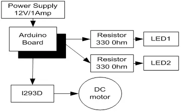
Block diagram to control DC motor with L293D.
5.2.1. Circuit Diagram
Connect all the components to Arduino as per the connections as described-
- Input pins 2 and 7 of L293D IC are connected to 10 and 9 pins of Arduino Uno.
- Output pins 3 and 8 of L293D IC are connected to +ve and –ve terminals of DC motor respectively.
- +12V DC jack of power supply is connected to DC jack of Arduino Uno.
- Pins 1,9 and 16 of L293D are connected to +5V.
- Pins 4,5 and 12, 13 of L293D are connected to GND.
- Pin 8 of L293D is connected to +12V power supply.
- LEDs are connected parallel to input pins 2 & 7 of L293D.
Fig. (5.5) shows circuit diagram to control DC motor with L293D.
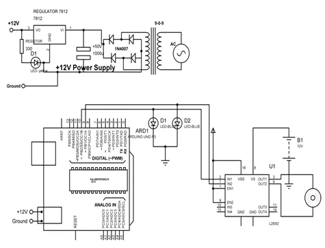
Circuit diagram to control DC motor with L293D.
5.2.2. Program
int MPIN1 = 10;
int MPIN2 = 9;
void setup()
{
// initialize the digital pin as an output.
pinMode(MPIN1, OUTPUT);
pinMode(MPIN2, OUTPUT);
}
void loop()
{
clockwise();
delay(2000); // wait for a 1000 millisecond
anticlockwise();
delay(2000); // wait for a 1000 millisecond
}
clockwise()
{
digitalWrite(MPIN1, HIGH); // make pin 10 as HIGH and 9 as LOW
digitalWrite(MPIN2, LOW);
}
anticlockwise()
{
digitalWrite(MPIN...