
eBook - ePub
Arduino meets MATLAB: Interfacing, Programs and Simulink
Anita Gehlot, Rajesh Singh, Bhupendra Singh
This is a test
Buch teilen
- English
- ePUB (handyfreundlich)
- Über iOS und Android verfügbar
eBook - ePub
Arduino meets MATLAB: Interfacing, Programs and Simulink
Anita Gehlot, Rajesh Singh, Bhupendra Singh
Angaben zum Buch
Buchvorschau
Inhaltsverzeichnis
Quellenangaben
Über dieses Buch
This book provides a single platform for beginners in systems engineering to start Arduino interface projects with MATLAB®. It covers the basics of the programming with Arduino and Arduino interfacing with MATLAB® with and without the use or I/O packages.
Häufig gestellte Fragen
Wie kann ich mein Abo kündigen?
Gehe einfach zum Kontobereich in den Einstellungen und klicke auf „Abo kündigen“ – ganz einfach. Nachdem du gekündigt hast, bleibt deine Mitgliedschaft für den verbleibenden Abozeitraum, den du bereits bezahlt hast, aktiv. Mehr Informationen hier.
(Wie) Kann ich Bücher herunterladen?
Derzeit stehen all unsere auf Mobilgeräte reagierenden ePub-Bücher zum Download über die App zur Verfügung. Die meisten unserer PDFs stehen ebenfalls zum Download bereit; wir arbeiten daran, auch die übrigen PDFs zum Download anzubieten, bei denen dies aktuell noch nicht möglich ist. Weitere Informationen hier.
Welcher Unterschied besteht bei den Preisen zwischen den Aboplänen?
Mit beiden Aboplänen erhältst du vollen Zugang zur Bibliothek und allen Funktionen von Perlego. Die einzigen Unterschiede bestehen im Preis und dem Abozeitraum: Mit dem Jahresabo sparst du auf 12 Monate gerechnet im Vergleich zum Monatsabo rund 30 %.
Was ist Perlego?
Wir sind ein Online-Abodienst für Lehrbücher, bei dem du für weniger als den Preis eines einzelnen Buches pro Monat Zugang zu einer ganzen Online-Bibliothek erhältst. Mit über 1 Million Büchern zu über 1.000 verschiedenen Themen haben wir bestimmt alles, was du brauchst! Weitere Informationen hier.
Unterstützt Perlego Text-zu-Sprache?
Achte auf das Symbol zum Vorlesen in deinem nächsten Buch, um zu sehen, ob du es dir auch anhören kannst. Bei diesem Tool wird dir Text laut vorgelesen, wobei der Text beim Vorlesen auch grafisch hervorgehoben wird. Du kannst das Vorlesen jederzeit anhalten, beschleunigen und verlangsamen. Weitere Informationen hier.
Ist Arduino meets MATLAB: Interfacing, Programs and Simulink als Online-PDF/ePub verfügbar?
Ja, du hast Zugang zu Arduino meets MATLAB: Interfacing, Programs and Simulink von Anita Gehlot, Rajesh Singh, Bhupendra Singh im PDF- und/oder ePub-Format sowie zu anderen beliebten Büchern aus Informatik & Programmierung. Aus unserem Katalog stehen dir über 1 Million Bücher zur Verfügung.
Information
Thema
InformatikThema
ProgrammierungArduino Interfacing with Actuators
Rajesh Singh, Anita Gehlot, Bhupendra Singh, Sushabhan Choudhury
Abstract
An actuator is a component which is responsible for moving or controlling a mechanism. An actuator requires a control signal and a source of energy. This chapter explains the working of actuator with the help of different methods.
Keywords: AC motor, Arduino, DC motor, L293D, Stepper motor, Servo motor.
5.1. DC motor control with transistor ‘H’ bridge
A DC motor is a device that converts electrical energy into mechanical energy. It has vital importance for the industry. Fig. (5.1) shows the block diagram of the system, comprises of Arduino, power supply, DC motor, LED. It is designed to control the DC motor with ‘H’ bridge (2N2222), LEDs are connected to check the change in the status of inputs to motor in order to make it move in forward and reverse direction. To make H bridge four 2N2222 transistors are used- Q1, Q2, Q3, Q4.
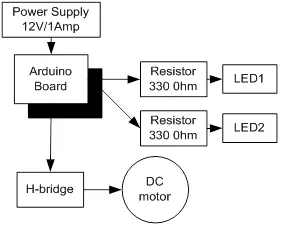
Block diagram for the interfacing of DC motor.
5.1.1. Circuit Diagram
Connect all the components to Arduino as per the connections as described-
- Make collector of Q1 & Q2 common and connect to positive terminal of +12V DC.
- Make emitter of Q3 & Q4 common and connect to negative terminal of +12V DC and ‘GND’.
- Make base of Q1 & Q4 common and connect to pin9 of Arduino.
- Make base of Q2 & Q3 common and connect to pin10 of Arduino.
- LEDs are also connected parallel to inputs of H -bridge.
- +12V DC jack of power supply is connected to DC jack of Arduino Uno.
Fig. (5.2) shows circuit diagram for the interfacing of DC motor.
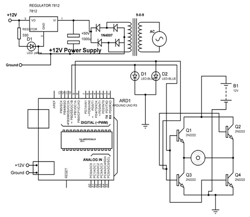
Circuit diagram for the interfacing of DC motor.
5.1.2. Program
int MPIN1 = 10;
int MPIN2 = 9;
void setup()
{
// initialize pin10 and 9 as output
pinMode(MPIN1, OUTPUT);
pinMode(MPIN2, OUTPUT);
}
void loop()
{
digitalWrite(MPIN1, HIGH); // make 10 and 9 pin HIGH and LOW respectively
digitalWrite(MPIN2, LOW);
delay(1000); // wait for a 1000 millisecond
digitalWrite(MPIN1, LOW); // make 9 and 10 pin HIGH and LOW respectively
digitalWrite(MPIN2, HIGH);
delay(1000); // wait for a 1000 millisecond
}
5.1.3. Proteus Simulation Model
Connect the components with Arduino as described in section 5.1.1 in the virtual environment of Proteus simulator. Power supply need not to be connected in the virtual environment of Proteus. Load the program as described in section 5.1.2 and check the feasibility and working of the circuit. Fig. (5.3) shows the Proteus model for the system.
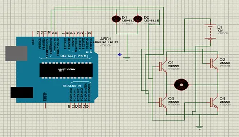
Proteus simulation model for the Arduino interfacing with DC motor.
5.2. DC motor control with L293D
L293D is 14 pin motor driver IC. DC motor upto 12V/1A ca be controlled with this.Fig. (5.4) shows the block diagram of the system, comprises of Arduino, power supply, DC motor, L293D, LED. It is designed to control the DC motor with IC L293D. LEDs are connected to check the change in the status of inputs to motor in order to make it move in forward and reverse direction.
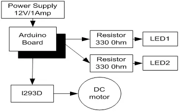
Block diagram to control DC motor with L293D.
5.2.1. Circuit Diagram
Connect all the components to Arduino as per the connections as described-
- Input pins 2 and 7 of L293D IC are connected to 10 and 9 pins of Arduino Uno.
- Output pins 3 and 8 of L293D IC are connected to +ve and –ve terminals of DC motor respectively.
- +12V DC jack of power supply is connected to DC jack of Arduino Uno.
- Pins 1,9 and 16 of L293D are connected to +5V.
- Pins 4,5 and 12, 13 of L293D are connected to GND.
- Pin 8 of L293D is connected to +12V power supply.
- LEDs are connected parallel to input pins 2 & 7 of L293D.
Fig. (5.5) shows circuit diagram to control DC motor with L293D.
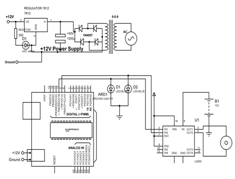
Circuit diagram to control DC motor with L293D.
5.2.2. Program
int MPIN1 = 10;
int MPIN2 = 9;
void setup()
{
// initialize the digital pin as an output.
pinMode(MPIN1, OUTPUT);
pinMode(MPIN2, OUTPUT);
}
void loop()
{
clockwise();
delay(2000); // wait for a 1000 millisecond
anticlockwise();
delay(2000); // wait for a 1000 millisecond
}
clockwise()
{
digitalWrite(MPIN1, HIGH); // make pin 10 as HIGH and 9 as LOW
digitalWrite(MPIN2, LOW);
}
anticlockwise()
{
digitalWrite(MPIN...