This book provides a single platform for beginners in systems engineering to start Arduino interface projects with MATLAB®. It covers the basics of the programming with Arduino and Arduino interfacing with MATLAB® with and without the use or I/O packages.

eBook - ePub
Arduino meets MATLAB: Interfacing, Programs and Simulink
- English
- ePUB (mobile friendly)
- Available on iOS & Android
eBook - ePub
Arduino meets MATLAB: Interfacing, Programs and Simulink
About this book
Trusted by 375,005 students
Access to over 1.5 million titles for a fair monthly price.
Study more efficiently using our study tools.
Information
Arduino Interfacing with Actuators
Rajesh Singh, Anita Gehlot, Bhupendra Singh, Sushabhan Choudhury
Abstract
An actuator is a component which is responsible for moving or controlling a mechanism. An actuator requires a control signal and a source of energy. This chapter explains the working of actuator with the help of different methods.
Keywords: AC motor, Arduino, DC motor, L293D, Stepper motor, Servo motor.
5.1. DC motor control with transistor ‘H’ bridge
A DC motor is a device that converts electrical energy into mechanical energy. It has vital importance for the industry. Fig. (5.1) shows the block diagram of the system, comprises of Arduino, power supply, DC motor, LED. It is designed to control the DC motor with ‘H’ bridge (2N2222), LEDs are connected to check the change in the status of inputs to motor in order to make it move in forward and reverse direction. To make H bridge four 2N2222 transistors are used- Q1, Q2, Q3, Q4.
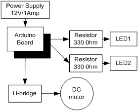
Block diagram for the interfacing of DC motor.
5.1.1. Circuit Diagram
Connect all the components to Arduino as per the connections as described-
- Make collector of Q1 & Q2 common and connect to positive terminal of +12V DC.
- Make emitter of Q3 & Q4 common and connect to negative terminal of +12V DC and ‘GND’.
- Make base of Q1 & Q4 common and connect to pin9 of Arduino.
- Make base of Q2 & Q3 common and connect to pin10 of Arduino.
- LEDs are also connected parallel to inputs of H -bridge.
- +12V DC jack of power supply is connected to DC jack of Arduino Uno.
Fig. (5.2) shows circuit diagram for the interfacing of DC motor.
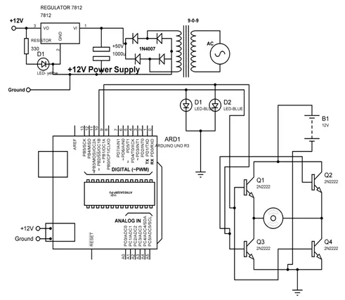
Circuit diagram for the interfacing of DC motor.
5.1.2. Program
int MPIN1 = 10;
int MPIN2 = 9;
void setup()
{
// initialize pin10 and 9 as output
pinMode(MPIN1, OUTPUT);
pinMode(MPIN2, OUTPUT);
}
void loop()
{
digitalWrite(MPIN1, HIGH); // make 10 and 9 pin HIGH and LOW respectively
digitalWrite(MPIN2, LOW);
delay(1000); // wait for a 1000 millisecond
digitalWrite(MPIN1, LOW); // make 9 and 10 pin HIGH and LOW respectively
digitalWrite(MPIN2, HIGH);
delay(1000); // wait for a 1000 millisecond
}
5.1.3. Proteus Simulation Model
Connect the components with Arduino as described in section 5.1.1 in the virtual environment of Proteus simulator. Power supply need not to be connected in the virtual environment of Proteus. Load the program as described in section 5.1.2 and check the feasibility and working of the circuit. Fig. (5.3) shows the Proteus model for the system.
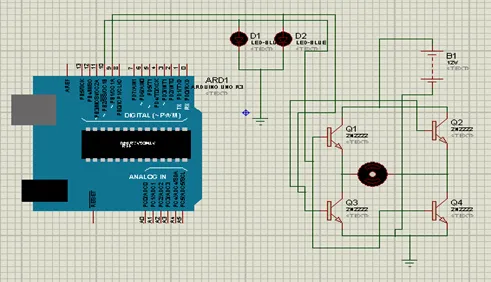
Proteus simulation model for the Arduino interfacing with DC motor.
5.2. DC motor control with L293D
L293D is 14 pin motor driver IC. DC motor upto 12V/1A ca be controlled with this.Fig. (5.4) shows the block diagram of the system, comprises of Arduino, power supply, DC motor, L293D, LED. It is designed to control the DC motor with IC L293D. LEDs are connected to check the change in the status of inputs to motor in order to make it move in forward and reverse direction.
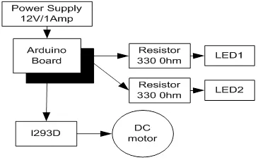
Block diagram to control DC motor with L293D.
5.2.1. Circuit Diagram
Connect all the components to Arduino as per the connections as described-
- Input pins 2 and 7 of L293D IC are connected to 10 and 9 pins of Arduino Uno.
- Output pins 3 and 8 of L293D IC are connected to +ve and –ve terminals of DC motor respectively.
- +12V DC jack of power supply is connected to DC jack of Arduino Uno.
- Pins 1,9 and 16 of L293D are connected to +5V.
- Pins 4,5 and 12, 13 of L293D are connected to GND.
- Pin 8 of L293D is connected to +12V power supply.
- LEDs are connected parallel to input pins 2 & 7 of L293D.
Fig. (5.5) shows circuit diagram to control DC motor with L293D.
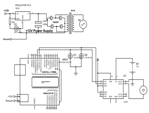
Circuit diagram to control DC motor with L293D.
5.2.2. Program
int MPIN1 = 10;
int MPIN2 = 9;
void setup()
{
// initialize the digital pin as an output.
pinMode(MPIN1, OUTPUT);
pinMode(MPIN2, OUTPUT);
}
void loop()
{
clockwise();
delay(2000); // wait for a 1000 millisecond
anticlockwise();
delay(2000); // wait for a 1000 millisecond
}
clockwise()
{
digitalWrite(MPIN1, HIGH); // make pin 10 as HIGH and 9 as LOW
digitalWrite(MPIN2, LOW);
}
anticlockwise()
{
digitalWrite(MPIN...
Table of contents
- Welcome
- Table of Contents
- Title
- BENTHAM SCIENCE PUBLISHERS LTD.
- FOREWORD
- PREFACE
- BIOGRAPHY OF AUTHORS
- SECTION A: Arduino and its Interfacing
- Introduction to Arduino, Arduino IDE and Proteus Software
- Arduino Interfacing with Display Devices
- Arduino Interfacing with Digital Sensors
- Arduino Interfacing with Analog Sensors
- Arduino Interfacing with Actuators
- Arduino Interfacing with Wireless Modems
- MATLAB GUI
- SECTION B: Arduino Interfacing with MATLAB using I/O Package
- Simulink and Arduino I/O Package
- Digital Read/Write and Analog Read/Write with Arduino I/O Package
- Digital Read with Proximity and Touch Sensor and Digital Write on LED with Arduino I/O Package
- Key Touch Sensor Based Home Automation with Arduino I/O Package
- Sun Tracker System Using LDR with Arduino I/O Package
- Robot Control and Sensor Data Acquisition System with Arduino I/O Package
- Two Analog Sensors [POT and LM35] Interfacing with Arduino I/O Package
- Three Sensors Data Acquisition and Feedback System with MATLAB and Arduino I/O Package
- SECTION C: Arduino Interfacing with MATLAB without I/O Package
- Building Automation System
- Robot Control with MATLAB GUI
- One Analog Channel and Digital Write Using MATLAB GUI
- Bibliography
- BIBLIOGRAPHY
Frequently asked questions
Yes, you can cancel anytime from the Subscription tab in your account settings on the Perlego website. Your subscription will stay active until the end of your current billing period. Learn how to cancel your subscription
No, books cannot be downloaded as external files, such as PDFs, for use outside of Perlego. However, you can download books within the Perlego app for offline reading on mobile or tablet. Learn how to download books offline
Perlego offers two plans: Essential and Complete
- Essential is ideal for learners and professionals who enjoy exploring a wide range of subjects. Access the Essential Library with 800,000+ trusted titles and best-sellers across business, personal growth, and the humanities. Includes unlimited reading time and Standard Read Aloud voice.
- Complete: Perfect for advanced learners and researchers needing full, unrestricted access. Unlock 1.5M+ books across hundreds of subjects, including academic and specialized titles. The Complete Plan also includes advanced features like Premium Read Aloud and Research Assistant.
We are an online textbook subscription service, where you can get access to an entire online library for less than the price of a single book per month. With over 1.5 million books across 990+ topics, we’ve got you covered! Learn about our mission
Look out for the read-aloud symbol on your next book to see if you can listen to it. The read-aloud tool reads text aloud for you, highlighting the text as it is being read. You can pause it, speed it up and slow it down. Learn more about Read Aloud
Yes! You can use the Perlego app on both iOS and Android devices to read anytime, anywhere — even offline. Perfect for commutes or when you’re on the go.
Please note we cannot support devices running on iOS 13 and Android 7 or earlier. Learn more about using the app
Please note we cannot support devices running on iOS 13 and Android 7 or earlier. Learn more about using the app
Yes, you can access Arduino meets MATLAB: Interfacing, Programs and Simulink by Anita Gehlot,Rajesh Singh,Bhupendra Singh in PDF and/or ePUB format, as well as other popular books in Computer Science & Programming. We have over 1.5 million books available in our catalogue for you to explore.