
eBook - ePub
Arduino meets MATLAB: Interfacing, Programs and Simulink
Anita Gehlot, Rajesh Singh, Bhupendra Singh
This is a test
Condividi libro
- English
- ePUB (disponibile sull'app)
- Disponibile su iOS e Android
eBook - ePub
Arduino meets MATLAB: Interfacing, Programs and Simulink
Anita Gehlot, Rajesh Singh, Bhupendra Singh
Dettagli del libro
Anteprima del libro
Indice dei contenuti
Citazioni
Informazioni sul libro
This book provides a single platform for beginners in systems engineering to start Arduino interface projects with MATLAB®. It covers the basics of the programming with Arduino and Arduino interfacing with MATLAB® with and without the use or I/O packages.
Domande frequenti
Come faccio ad annullare l'abbonamento?
È semplicissimo: basta accedere alla sezione Account nelle Impostazioni e cliccare su "Annulla abbonamento". Dopo la cancellazione, l'abbonamento rimarrà attivo per il periodo rimanente già pagato. Per maggiori informazioni, clicca qui
È possibile scaricare libri? Se sì, come?
Al momento è possibile scaricare tramite l'app tutti i nostri libri ePub mobile-friendly. Anche la maggior parte dei nostri PDF è scaricabile e stiamo lavorando per rendere disponibile quanto prima il download di tutti gli altri file. Per maggiori informazioni, clicca qui
Che differenza c'è tra i piani?
Entrambi i piani ti danno accesso illimitato alla libreria e a tutte le funzionalità di Perlego. Le uniche differenze sono il prezzo e il periodo di abbonamento: con il piano annuale risparmierai circa il 30% rispetto a 12 rate con quello mensile.
Cos'è Perlego?
Perlego è un servizio di abbonamento a testi accademici, che ti permette di accedere a un'intera libreria online a un prezzo inferiore rispetto a quello che pagheresti per acquistare un singolo libro al mese. Con oltre 1 milione di testi suddivisi in più di 1.000 categorie, troverai sicuramente ciò che fa per te! Per maggiori informazioni, clicca qui.
Perlego supporta la sintesi vocale?
Cerca l'icona Sintesi vocale nel prossimo libro che leggerai per verificare se è possibile riprodurre l'audio. Questo strumento permette di leggere il testo a voce alta, evidenziandolo man mano che la lettura procede. Puoi aumentare o diminuire la velocità della sintesi vocale, oppure sospendere la riproduzione. Per maggiori informazioni, clicca qui.
Arduino meets MATLAB: Interfacing, Programs and Simulink è disponibile online in formato PDF/ePub?
Sì, puoi accedere a Arduino meets MATLAB: Interfacing, Programs and Simulink di Anita Gehlot, Rajesh Singh, Bhupendra Singh in formato PDF e/o ePub, così come ad altri libri molto apprezzati nelle sezioni relative a Informatik e Programmierung. Scopri oltre 1 milione di libri disponibili nel nostro catalogo.
Informazioni
Argomento
InformatikCategoria
ProgrammierungArduino Interfacing with Actuators
Rajesh Singh, Anita Gehlot, Bhupendra Singh, Sushabhan Choudhury
Abstract
An actuator is a component which is responsible for moving or controlling a mechanism. An actuator requires a control signal and a source of energy. This chapter explains the working of actuator with the help of different methods.
Keywords: AC motor, Arduino, DC motor, L293D, Stepper motor, Servo motor.
5.1. DC motor control with transistor ‘H’ bridge
A DC motor is a device that converts electrical energy into mechanical energy. It has vital importance for the industry. Fig. (5.1) shows the block diagram of the system, comprises of Arduino, power supply, DC motor, LED. It is designed to control the DC motor with ‘H’ bridge (2N2222), LEDs are connected to check the change in the status of inputs to motor in order to make it move in forward and reverse direction. To make H bridge four 2N2222 transistors are used- Q1, Q2, Q3, Q4.
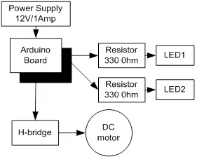
Block diagram for the interfacing of DC motor.
5.1.1. Circuit Diagram
Connect all the components to Arduino as per the connections as described-
- Make collector of Q1 & Q2 common and connect to positive terminal of +12V DC.
- Make emitter of Q3 & Q4 common and connect to negative terminal of +12V DC and ‘GND’.
- Make base of Q1 & Q4 common and connect to pin9 of Arduino.
- Make base of Q2 & Q3 common and connect to pin10 of Arduino.
- LEDs are also connected parallel to inputs of H -bridge.
- +12V DC jack of power supply is connected to DC jack of Arduino Uno.
Fig. (5.2) shows circuit diagram for the interfacing of DC motor.
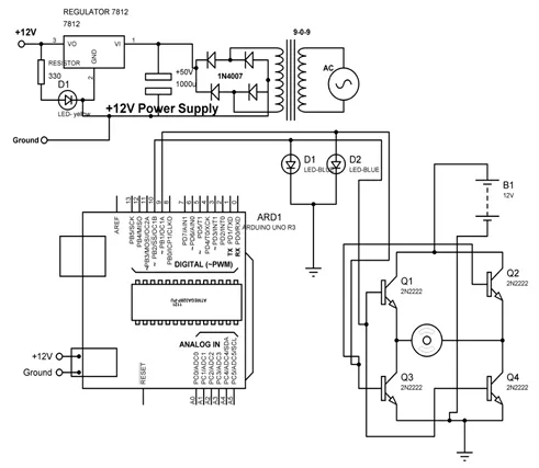
Circuit diagram for the interfacing of DC motor.
5.1.2. Program
int MPIN1 = 10;
int MPIN2 = 9;
void setup()
{
// initialize pin10 and 9 as output
pinMode(MPIN1, OUTPUT);
pinMode(MPIN2, OUTPUT);
}
void loop()
{
digitalWrite(MPIN1, HIGH); // make 10 and 9 pin HIGH and LOW respectively
digitalWrite(MPIN2, LOW);
delay(1000); // wait for a 1000 millisecond
digitalWrite(MPIN1, LOW); // make 9 and 10 pin HIGH and LOW respectively
digitalWrite(MPIN2, HIGH);
delay(1000); // wait for a 1000 millisecond
}
5.1.3. Proteus Simulation Model
Connect the components with Arduino as described in section 5.1.1 in the virtual environment of Proteus simulator. Power supply need not to be connected in the virtual environment of Proteus. Load the program as described in section 5.1.2 and check the feasibility and working of the circuit. Fig. (5.3) shows the Proteus model for the system.
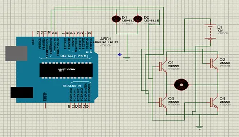
Proteus simulation model for the Arduino interfacing with DC motor.
5.2. DC motor control with L293D
L293D is 14 pin motor driver IC. DC motor upto 12V/1A ca be controlled with this.Fig. (5.4) shows the block diagram of the system, comprises of Arduino, power supply, DC motor, L293D, LED. It is designed to control the DC motor with IC L293D. LEDs are connected to check the change in the status of inputs to motor in order to make it move in forward and reverse direction.
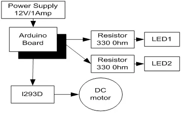
Block diagram to control DC motor with L293D.
5.2.1. Circuit Diagram
Connect all the components to Arduino as per the connections as described-
- Input pins 2 and 7 of L293D IC are connected to 10 and 9 pins of Arduino Uno.
- Output pins 3 and 8 of L293D IC are connected to +ve and –ve terminals of DC motor respectively.
- +12V DC jack of power supply is connected to DC jack of Arduino Uno.
- Pins 1,9 and 16 of L293D are connected to +5V.
- Pins 4,5 and 12, 13 of L293D are connected to GND.
- Pin 8 of L293D is connected to +12V power supply.
- LEDs are connected parallel to input pins 2 & 7 of L293D.
Fig. (5.5) shows circuit diagram to control DC motor with L293D.
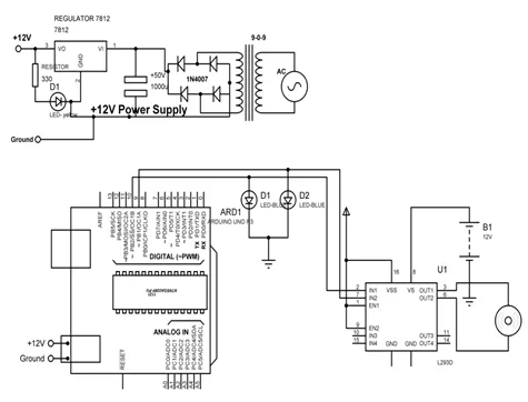
Circuit diagram to control DC motor with L293D.
5.2.2. Program
int MPIN1 = 10;
int MPIN2 = 9;
void setup()
{
// initialize the digital pin as an output.
pinMode(MPIN1, OUTPUT);
pinMode(MPIN2, OUTPUT);
}
void loop()
{
clockwise();
delay(2000); // wait for a 1000 millisecond
anticlockwise();
delay(2000); // wait for a 1000 millisecond
}
clockwise()
{
digitalWrite(MPIN1, HIGH); // make pin 10 as HIGH and 9 as LOW
digitalWrite(MPIN2, LOW);
}
anticlockwise()
{
digitalWrite(MPIN...