
eBook - ePub
Arduino meets MATLAB: Interfacing, Programs and Simulink
Anita Gehlot, Rajesh Singh, Bhupendra Singh
This is a test
Partager le livre
- English
- ePUB (adapté aux mobiles)
- Disponible sur iOS et Android
eBook - ePub
Arduino meets MATLAB: Interfacing, Programs and Simulink
Anita Gehlot, Rajesh Singh, Bhupendra Singh
Détails du livre
Aperçu du livre
Table des matières
Citations
À propos de ce livre
This book provides a single platform for beginners in systems engineering to start Arduino interface projects with MATLAB®. It covers the basics of the programming with Arduino and Arduino interfacing with MATLAB® with and without the use or I/O packages.
Foire aux questions
Comment puis-je résilier mon abonnement ?
Il vous suffit de vous rendre dans la section compte dans paramètres et de cliquer sur « Résilier l’abonnement ». C’est aussi simple que cela ! Une fois que vous aurez résilié votre abonnement, il restera actif pour le reste de la période pour laquelle vous avez payé. Découvrez-en plus ici.
Puis-je / comment puis-je télécharger des livres ?
Pour le moment, tous nos livres en format ePub adaptés aux mobiles peuvent être téléchargés via l’application. La plupart de nos PDF sont également disponibles en téléchargement et les autres seront téléchargeables très prochainement. Découvrez-en plus ici.
Quelle est la différence entre les formules tarifaires ?
Les deux abonnements vous donnent un accès complet à la bibliothèque et à toutes les fonctionnalités de Perlego. Les seules différences sont les tarifs ainsi que la période d’abonnement : avec l’abonnement annuel, vous économiserez environ 30 % par rapport à 12 mois d’abonnement mensuel.
Qu’est-ce que Perlego ?
Nous sommes un service d’abonnement à des ouvrages universitaires en ligne, où vous pouvez accéder à toute une bibliothèque pour un prix inférieur à celui d’un seul livre par mois. Avec plus d’un million de livres sur plus de 1 000 sujets, nous avons ce qu’il vous faut ! Découvrez-en plus ici.
Prenez-vous en charge la synthèse vocale ?
Recherchez le symbole Écouter sur votre prochain livre pour voir si vous pouvez l’écouter. L’outil Écouter lit le texte à haute voix pour vous, en surlignant le passage qui est en cours de lecture. Vous pouvez le mettre sur pause, l’accélérer ou le ralentir. Découvrez-en plus ici.
Est-ce que Arduino meets MATLAB: Interfacing, Programs and Simulink est un PDF/ePUB en ligne ?
Oui, vous pouvez accéder à Arduino meets MATLAB: Interfacing, Programs and Simulink par Anita Gehlot, Rajesh Singh, Bhupendra Singh en format PDF et/ou ePUB ainsi qu’à d’autres livres populaires dans Informatik et Programmierung. Nous disposons de plus d’un million d’ouvrages à découvrir dans notre catalogue.
Informations
Sujet
InformatikSous-sujet
ProgrammierungArduino Interfacing with Actuators
Rajesh Singh, Anita Gehlot, Bhupendra Singh, Sushabhan Choudhury
Abstract
An actuator is a component which is responsible for moving or controlling a mechanism. An actuator requires a control signal and a source of energy. This chapter explains the working of actuator with the help of different methods.
Keywords: AC motor, Arduino, DC motor, L293D, Stepper motor, Servo motor.
5.1. DC motor control with transistor ‘H’ bridge
A DC motor is a device that converts electrical energy into mechanical energy. It has vital importance for the industry. Fig. (5.1) shows the block diagram of the system, comprises of Arduino, power supply, DC motor, LED. It is designed to control the DC motor with ‘H’ bridge (2N2222), LEDs are connected to check the change in the status of inputs to motor in order to make it move in forward and reverse direction. To make H bridge four 2N2222 transistors are used- Q1, Q2, Q3, Q4.
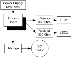
Block diagram for the interfacing of DC motor.
5.1.1. Circuit Diagram
Connect all the components to Arduino as per the connections as described-
- Make collector of Q1 & Q2 common and connect to positive terminal of +12V DC.
- Make emitter of Q3 & Q4 common and connect to negative terminal of +12V DC and ‘GND’.
- Make base of Q1 & Q4 common and connect to pin9 of Arduino.
- Make base of Q2 & Q3 common and connect to pin10 of Arduino.
- LEDs are also connected parallel to inputs of H -bridge.
- +12V DC jack of power supply is connected to DC jack of Arduino Uno.
Fig. (5.2) shows circuit diagram for the interfacing of DC motor.
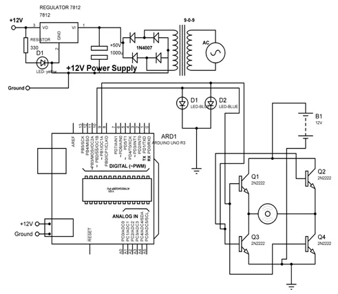
Circuit diagram for the interfacing of DC motor.
5.1.2. Program
int MPIN1 = 10;
int MPIN2 = 9;
void setup()
{
// initialize pin10 and 9 as output
pinMode(MPIN1, OUTPUT);
pinMode(MPIN2, OUTPUT);
}
void loop()
{
digitalWrite(MPIN1, HIGH); // make 10 and 9 pin HIGH and LOW respectively
digitalWrite(MPIN2, LOW);
delay(1000); // wait for a 1000 millisecond
digitalWrite(MPIN1, LOW); // make 9 and 10 pin HIGH and LOW respectively
digitalWrite(MPIN2, HIGH);
delay(1000); // wait for a 1000 millisecond
}
5.1.3. Proteus Simulation Model
Connect the components with Arduino as described in section 5.1.1 in the virtual environment of Proteus simulator. Power supply need not to be connected in the virtual environment of Proteus. Load the program as described in section 5.1.2 and check the feasibility and working of the circuit. Fig. (5.3) shows the Proteus model for the system.
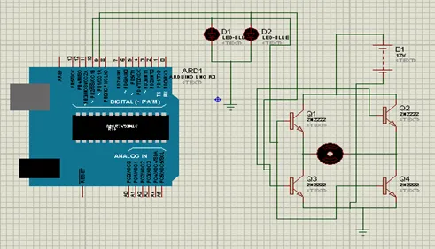
Proteus simulation model for the Arduino interfacing with DC motor.
5.2. DC motor control with L293D
L293D is 14 pin motor driver IC. DC motor upto 12V/1A ca be controlled with this.Fig. (5.4) shows the block diagram of the system, comprises of Arduino, power supply, DC motor, L293D, LED. It is designed to control the DC motor with IC L293D. LEDs are connected to check the change in the status of inputs to motor in order to make it move in forward and reverse direction.
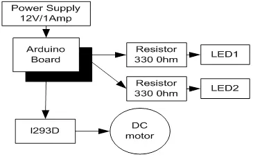
Block diagram to control DC motor with L293D.
5.2.1. Circuit Diagram
Connect all the components to Arduino as per the connections as described-
- Input pins 2 and 7 of L293D IC are connected to 10 and 9 pins of Arduino Uno.
- Output pins 3 and 8 of L293D IC are connected to +ve and –ve terminals of DC motor respectively.
- +12V DC jack of power supply is connected to DC jack of Arduino Uno.
- Pins 1,9 and 16 of L293D are connected to +5V.
- Pins 4,5 and 12, 13 of L293D are connected to GND.
- Pin 8 of L293D is connected to +12V power supply.
- LEDs are connected parallel to input pins 2 & 7 of L293D.
Fig. (5.5) shows circuit diagram to control DC motor with L293D.
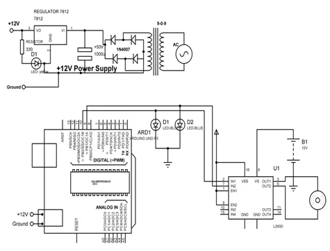
Circuit diagram to control DC motor with L293D.
5.2.2. Program
int MPIN1 = 10;
int MPIN2 = 9;
void setup()
{
// initialize the digital pin as an output.
pinMode(MPIN1, OUTPUT);
pinMode(MPIN2, OUTPUT);
}
void loop()
{
clockwise();
delay(2000); // wait for a 1000 millisecond
anticlockwise();
delay(2000); // wait for a 1000 millisecond
}
clockwise()
{
digitalWrite(MPIN1, HIGH); // make pin 10 as HIGH and 9 as LOW
digitalWrite(MPIN2, LOW);
}
anticlockwise()
{
digitalWrite(MPIN...