Technology & Engineering
Propeller
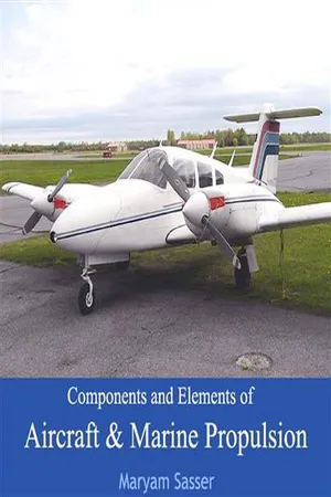
A propeller is a type of fan-like device that converts rotational motion into thrust. It is commonly used in aircraft, boats, and other vehicles to propel them through air or water. Propellers are designed with curved blades to efficiently move air or water, and they play a crucial role in the propulsion systems of various machines.
Written by Perlego with AI-assistance
5 Key excerpts on "Propeller"
 No longer available |Learn more
- (Author)
- 2014(Publication Date)
- Orange Apple(Publisher)
____________________ WORLD TECHNOLOGIES ____________________ Chapter- 1 Propeller Rotating the Hamilton Standard 54H60 Propeller on a US Navy EP-3E Orion's number four engine as part of pre-flight checks A Propeller is a type of fan that transmits power by converting rotational motion into thrust. A pressure difference is produced between the forward and rear surfaces of the airfoil-shaped blade, and air or water is accelerated behind the blade. Propeller dynamics ____________________ WORLD TECHNOLOGIES ____________________ can be modeled by both Bernoulli's principle and Newton's third law. A Propeller is often colloquially known as screw both in aviation and maritime. History Ship Propeller from 1843. Designed by C F Wahlgren based on one of John Ericsson Propellers. It was fitted to the steam ship s/s Flygfisken built at the Motala dockyard. The principle employed in using a screw Propeller is used in sculling. It is part of the skill of propelling a Venetian gondola but was used in a less refined way in other parts of Europe and probably elsewhere. For example, propelling a canoe with a single paddle ____________________ WORLD TECHNOLOGIES ____________________ using a j-stroke involves a related but not identical technique. In China, sculling, called lu, was also used by the 3rd century AD. In sculling, a single blade is moved through an arc, from side to side taking care to keep presenting the blade to the water at the effective angle. The innovation introduced with the screw Propeller was the extension of that arc through more than 360° by attaching the blade to a rotating shaft. Propellers can have a single blade, but in practice there are nearly always more than one so as to balance the forces involved. The origin of the actual screw Propeller starts with Archimedes, who used a screw to lift water for irrigation and bailing boats, so famously that it became known as Archimedes' screw. No longer available |Learn more
- (Author)
- 2014(Publication Date)
- Orange Apple(Publisher)
________________________ WORLD TECHNOLOGIES ________________________ Chapter 4 Propeller Rotating the Hamilton Standard 54H60 Propeller on a US Navy EP-3E Orion's number four engine as part of pre-flight checks ________________________ WORLD TECHNOLOGIES ________________________ A Propeller is a type of fan that transmits power by converting rotational motion into thrust. A pressure difference is produced between the forward and rear surfaces of the airfoil-shaped blade, and air or water is accelerated behind the blade. Propeller dynamics can be modeled by both Bernoulli's principle and Newton's third law. A Propeller is often colloquially known as screw both in aviation and maritime. History Ship Propeller from 1843. Designed by C F Wahlgren based on one of John Ericsson Propellers. It was fitted to the steam ship s/s Flygfisken built at the Motala dockyard. The principle employed in using a screw Propeller is used in sculling. It is part of the skill of propelling a Venetian gondola but was used in a less refined way in other parts of ________________________ WORLD TECHNOLOGIES ________________________ Europe and probably elsewhere. For example, propelling a canoe with a single paddle using a j-stroke involves a related but not identical technique. In China, sculling, called lu, was also used by the 3rd century AD. In sculling, a single blade is moved through an arc, from side to side taking care to keep presenting the blade to the water at the effective angle. The innovation introduced with the screw Propeller was the extension of that arc through more than 360° by attaching the blade to a rotating shaft. Propellers can have a single blade, but in practice there are nearly always more than one so as to balance the forces involved. The origin of the actual screw Propeller starts with Archimedes, who used a screw to lift water for irrigation and bailing boats, so famously that it became known as Archimedes' screw. No longer available |Learn more
- (Author)
- 2014(Publication Date)
- Academic Studio(Publisher)
________________________ WORLD TECHNOLOGIES ________________________ Chapter 10 Propeller Rotating the Hamilton Standard 54H60 Propeller on a US Navy EP-3E Orion's number four engine as part of pre-flight checks ________________________ WORLD TECHNOLOGIES ________________________ A Propeller is a type of fan that transmits power by converting rotational motion into thrust. A pressure difference is produced between the forward and rear surfaces of the airfoil-shaped blade, and air or water is accelerated behind the blade. Propeller dynamics can be modeled by both Bernoulli's principle and Newton's third law. A Propeller is often colloquially known as screw both in aviation and maritime. History Ship Propeller from 1843. Designed by C F Wahlgren based on one of John Ericsson Propellers. It was fitted to the steam ship s/s Flygfisken built at the Motala dockyard. The principle employed in using a screw Propeller is used in sculling. It is part of the skill of propelling a Venetian gondola but was used in a less refined way in other parts of ________________________ WORLD TECHNOLOGIES ________________________ Europe and probably elsewhere. For example, propelling a canoe with a single paddle using a j-stroke involves a related but not identical technique. In China, sculling, called lu, was also used by the 3rd century AD. In sculling, a single blade is moved through an arc, from side to side taking care to keep presenting the blade to the water at the effective angle. The innovation introduced with the screw Propeller was the extension of that arc through more than 360° by attaching the blade to a rotating shaft. Propellers can have a single blade, but in practice there are nearly always more than one so as to balance the forces involved. The origin of the actual screw Propeller starts with Archimedes, who used a screw to lift water for irrigation and bailing boats, so famously that it became known as Archimedes' screw. eBook - ePub
- (Author)
- 2023(Publication Date)
- Aviation Supplies & Academics, Inc.(Publisher)
The aircraft Propeller consists of two or more blades and a central hub to which the blades are attached. Each blade of an aircraft Propeller is essentially a rotating wing. As a result of their construction, the Propeller blades produce forces that create thrust to pull or push the aircraft through the air. The power needed to rotate the Propeller blades is furnished by the engine. The Propeller is mounted on a shaft, which may be an extension of the crankshaft on low-horsepower engines; on high-horsepower engines, it is mounted on a Propeller shaft that is geared to the engine crankshaft. In either case, the engine rotates the airfoils of the blades through the air at high speeds, and the Propeller transforms the rotary power of the engine into thrust.Propeller Aerodynamic Process
An aircraft moving through the air creates a drag force opposing its forward motion. If an aircraft is to fly on a level path, there must be a force applied to it that is equal to the drag but acting forward. This force is called thrust. The work done by thrust is equal to the thrust times the distance it moves the aircraft.The power expended by thrust is equal to the thrust times the velocity at which it moves the aircraft. If the power is measured in horsepower units, the power expended by the thrust is termed thrust horsepower.The engine supplies brake horsepower through a rotating shaft, and the Propeller converts it into thrust horsepower. In this conversion, some power is wasted. For maximum efficiency, the Propeller must be designed to keep this waste as small as possible. Since the efficiency of any machine is the ratio of the useful power output to the power input, Propeller efficiency is the ratio of thrust horsepower to brake horsepower. The usual symbol for Propeller efficiency is the Greek letter η (eta). Propeller efficiency varies from 50 percent to 87 percent, depending on how much the Propeller slips.Pitch is not the same as blade angle, but because pitch is largely determined by blade angle, the two terms are often used interchangeably. An increase or decrease in one is usually associated with an increase or decrease in the other. Propeller slip is the difference between the geometric pitch of the Propeller and its effective pitch. [Figure 7-4] eBook - ePub
- Dale De Remer(Author)
- 2018(Publication Date)
- Aviation Supplies & Academics, Inc.(Publisher)
The power needed to rotate the Propeller blades is furnished by the engine. The Propeller is mounted on a shaft, which may be an extension of the crankshaft on low-horsepower engines; on high-horsepower engines, it is mounted on a Propeller shaft which is geared to the engine crankshaft. In either case, the engine rotates the airfoils of the blades through the air at high speeds, and the Propeller transforms the rotary motion (power) of the engine into thrust.The engine supplies brake horsepower through a rotating shaft. and the Propeller converts it into thrust horsepower . In this conversion, some power is wasted. For maximum efficiency, the Propeller must be designed to keep this waste as small as possible. Since the efficiency of any machine is the ratio of the useful power output to the power input, Propeller efficiency is the ratio of thrust horsepower to brake horsepower. The usual symbol for Propeller efficiency is the Greek letter η (eta). Propeller efficiency varies from 50% to 87%, depending on how much the Propeller “slips.”THP = BHP × Propeller EfficiencyPropeller slip is the difference between the geometric pitch of the Propeller and its effective pitch (see figure 5-1). Geometric pitch is the distance a Propeller should advance in one revolution; effective pitch is the distance it actually advances. Thus, geometric or theoretical pitch is based on no slippage, but actual, or effective pitch, recognizes Propeller slippage in the air.Figure 5-1. Effective and geometric pitch.The typical Propeller blade can be described as a twisted airfoil of irregular planform. Two views of a Propeller blade are shown in figure 5-2. For purposes of analysis, a blade can be divided into segments, which are located by station numbers in inches from the center of the blade hub. The cross sections of each 6-in. blade segment are shown as airfoils in the right-hand side of figure 5-2. Also identified in figure 5-2 are the blade shank and the blade butt. The blade shank is the thick, rounded portion of the Propeller blade near the hub, which is designed to give strength to the blade. The blade butt, also called the blade base or root, is the end of the blade that fits in the Propeller hub. The blade tip is that part of the Propeller blade farthest from the hub, generally defined as the last 6 in. of the blade.
Index pages curate the most relevant extracts from our library of academic textbooks. They’ve been created using an in-house natural language model (NLM), each adding context and meaning to key research topics.